User Manual
Version 1.1 Published October 2014 Copyright©2014 ASRock INC. All rights reserved. Copyright Notice: No part of this documentation may be reproduced, transcribed, transmitted, or translated in any language, in any form or by any means, except duplication of documentation by the purchaser for backup purpose, without written consent of ASRock Inc.
Contents Chapter 1 Introduction 1 1.1 Package Contents 1 1.2 Speciications 2 1.3 Unique Features 6 1.4 Motherboard Layout 9 1.5 I/O Panel 11 Chapter 2 Installation 12 2.1 Installing the CPU 13 2.2 Installing the CPU Fan and Heatsink 15 2.3 Installing Memory Modules (DIMM) 16 2.4 Expansion Slots (PCI Express Slots) 18 2.5 Jumpers Setup 19 2.6 Onboard Headers and Connectors 20 Chapter 3 Software and Utilities Operation 24 3.1 Installing Drivers 24 3.
.3 OC Tweaker Screen 34 4.4 Advanced Screen 37 4.4.1 CPU Coniguration 38 4.4.2 Chipset Coniguration 39 4.4.3 Storage Coniguration 41 4.4.4 Super IO Coniguration 42 4.4.5 ACPI Coniguration 43 4.4.6 USB Coniguration 45 4.4.7 Trusted Computing 46 4.5 Tools 47 4.6 Hardware Health Event Monitoring Screen 50 4.7 Boot Screen 51 4.8 Security Screen 54 4.
AM1B-ITX Chapter 1 Introduction hank you for purchasing ASRock AM1B-ITX motherboard, a reliable motherboard produced under ASRock’s consistently stringent quality control. It delivers excellent performance with robust design conforming to ASRock’s commitment to quality and endurance. In this manual, Chapter 1 and 2 contains the introduction of the motherboard and step-by-step installation guides. Chapter 3 contains the operation guide of the sotware and utilities.
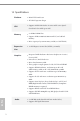
1.2 Speciications Platform • Mini-ITX Form Factor • All Solid Capacitor design CPU • Supports AMD AM1 Socket A-series and E-series QuadCore/Dual-Core APU up to 25W Memory • 2 x DDR3 DIMM Slots • Supports DDR3 1600/1333/1066 non-ECC, un-bufered memory • Max. capacity of system memory: 32GB (see CAUTION1) Expansion Slot • 1 x PCI Express 2.0 x16 Slot (PCIE1 @ x4 mode) Graphics TM • Integrated AMD Radeon R3 Series Graphics in A-series / E-series APU • DirectX 11.1, Pixel Shader 5.0 • Max.
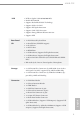
AM1B-ITX LAN • PCIE x1 Gigabit LAN 10/100/1000 Mb/s • Realtek RTL8111GR • Supports Realtek RealWoW! Technology • Supports Wake-On-LAN • Supports Full Spike Protection • Supports LAN Cable Detection • Supports Energy Eicient Ethernet 802.3az • Supports PXE Rear Panel I/O • 1 x PS/2 Mouse/Keyboard Port • 1 x Parallel Port (ECP/EPP support) • 1 x D-Sub Port • 1 x DVI-D Port • 1 x HDMI Port • 2 x USB 2.0 Ports (Supports Full Spike Protection) • 2 x USB 3.
BIOS Feature • 32Mb AMI UEFI Legal BIOS with GUI support • Supports “Plug and Play” • ACPI 1.1 compliance wake up events • Supports jumperfree • SMBIOS 2.3.
AM1B-ITX Please realize that there is a certain risk involved with overclocking, including adjusting the setting in the BIOS, applying Untied Overclocking Technology, or using thirdparty overclocking tools. Overclocking may afect your system’s stability, or even cause damage to the components and devices of your system. It should be done at your own risk and expense. We are not responsible for possible damage caused by overclocking.
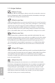
1.3 Unique Features ASRock A-Tuning A-Tuning is ASRock’s multi purpose sotware suite with a new interface, more new features and improved utilities, including XFast RAM, Dehumidiier, Good Night LED, FAN-Tastic Tuning and a whole lot more. ASRock Instant Boot ASRock Instant Boot allows you to turn on your PC in just a few seconds, provides a much more eicient way to save energy, time, money, and improves system running speed for your system.
AM1B-ITX ASRock XFast RAM ASRock XFast RAM is included in A-Tuning. It fully utilizes the memory space that cannot be used under Windows® 32-bit operating systems. ASRock XFast RAM shortens the loading time of previously visited websites, making web suring faster than ever. And it also boosts the speed of Adobe Photoshop 5 times faster. Another advantage of ASRock XFast RAM is that it reduces the frequency of accessing your SSDs or HDDs in order to extend their lifespan.
ASRock Easy Driver Installer For users that don’t have an optical disk drive to install the drivers from our support CD, Easy Driver Installer is a handy tool in the UEFI that installs the LAN driver to your system via an USB storage device, then downloads and installs the other required drivers automatically. ASRock Interactive UEFI ASRock Interactive UEFI is a blend of system coniguration tools, cool sound efects and stunning visuals.
AM1B-ITX 1.4 Motherboard Layout PS2 Keyboard/ Mouse Front USB 3.0 RoHS 1 USB 2.
No. Description English 10 1 Power Fan Connector (PWR_FAN1) 2 Clear CMOS Jumper (CLRCMOS1) 3 CPU Fan Connector (CPU_FAN1) 4 Chassis Intrusion Header (CI1) 5 2 x 240-pin DDR3 DIMM Slots (DDR3_A1, DDR3_A2) 6 ATX Power Connector (ATXPWR1) 7 Chassis Speaker Header (SPEAKER1) 8 System Panel Header (PANEL1) 9 SATA3 Connector (SATA3_1) 10 SATA3 Connector (SATA3_2) 11 SATA3 Connector (SATA3_A2) 12 SATA3 Connector (SATA3_A1) 13 Chassis Fan Connector (CHA_FAN1) 14 USB 3.
AM1B-ITX 1.5 I/O Panel 1 2 11 10 9 8 3 4 5 7 6 No. Description No. Description 1 USB 2.0 Ports (USB01) 7 USB 3.0 Ports (USB3_0_1) 2 Parallel Port 8 HDMI Port 3 LAN RJ-45 Port* 9 DVI-D Port 4 Line In (Light Blue) 10 D-Sub Port 5 Front Speaker (Lime) 11 PS/2 Mouse/Keyboard Port 6 Microphone (Pink) * here are two LEDs on each LAN port. Please refer to the table below for the LAN port LED indications.
Chapter 2 Installation his is a Mini-ITX form factor motherboard. Before you install the motherboard, study the coniguration of your chassis to ensure that the motherboard its into it. Pre-installation Precautions Take note of the following precautions before you install motherboard components or change any motherboard settings. • Make sure to unplug the power cord before installing or removing the motherboard. Failure to do so may cause physical injuries to you and damages to motherboard components.
AM1B-ITX 2.1 Installing the CPU Unplug all power cables before installing the CPU.
14 3 English
AM1B-ITX 2.2 Installing the CPU Fan and Heatsink Ater you install the CPU into this motherboard, it is necessary to install a larger heatsink and cooling fan to dissipate heat. You also need to spray thermal grease between the CPU and the heatsink to improve heat dissipation. Make sure that the CPU and the heatsink are securely fastened and in good contact with each other. hen connect the CPU fan to the CPU FAN connector.
2.3 Installing Memory Modules (DIMM) his motherboard provides two 240-pin DDR3 (Double Data Rate 3) DIMM slots. It is not allowed to install a DDR or DDR2 memory module into a DDR3 slot; otherwise, this motherboard and DIMM may be damaged. he DIMM only its in one correct orientation. It will cause permanent damage to the motherboard and the DIMM if you force the DIMM into the slot at incorrect orientation.
AM1B-ITX 1 2 English 3 17
2.4 Expansion Slot (PCI Express Slot) here is 1 PCI Express slot on the motherboard. Before installing an expansion card, please make sure that the power supply is switched of or the power cord is unplugged. Please read the documentation of the expansion card and make necessary hardware settings for the card before you start the installation. PCIe slot: PCIE1 (PCIe 2.0 x16 slot) is used for PCI Express x4 lane width graphics cards.
AM1B-ITX 2.5 Jumpers Setup he illustration shows how jumpers are setup. When the jumper cap is placed on the pins, the jumper is “Short”. If no jumper cap is placed on the pins, the jumper is “Open”. he illustration shows a 3-pin jumper whose pin1 and pin2 are “Short” when a jumper cap is placed on these 2 pins. Clear CMOS Jumper (CLRCMOS1) (see p.9, No. 2) Default Clear CMOS CLRCMOS1 allows you to clear the data in CMOS.
2.6 Onboard Headers and Connectors Onboard headers and connectors are NOT jumpers. Do NOT place jumper caps over these headers and connectors. Placing jumper caps over the headers and connectors will cause permanent damage to the motherboard. System Panel Header (9-pin PANEL1) (see p.9, No. 8) Connect the power switch, reset switch and system status indicator on the chassis to this header according to the pin assignments below. Note the positive and negative pins before connecting the cables.
hese four SATA3 connectors support SATA data cables for internal storage devices with up to 6.0 Gb/s data transfer rate. SATA3_A2 SATA3_2 USB 2.0 Headers (9-pin USB4_5) (see p.9, No. 17) (9-pin USB6_7) (see p.9, No. 18) USB 3.0 Header (19-pin USB3_2_3) (see p.9, No. 14) Besides two USB 2.0 ports on the I/O panel, there are two headers on this motherboard. Each USB 2.0 header can support two ports.
1. High Deinition Audio supports Jack Sensing, but the panel wire on the chassis must support HDA to function correctly. Please follow the instructions in our manual and chassis manual to install your system. 2. If you use an AC’97 audio panel, please install it to the front panel audio header by the steps below: A. Connect Mic_IN (MIC) to MIC2_L. B. Connect Audio_R (RIN) to OUT2_R and Audio_L (LIN) to OUT2_L. C. Connect Ground (GND) to Ground (GND). D. MIC_RET and OUT_RET are for the HD audio panel only.
SERIRQ# LAD0 GND GND +3V S_PWRDWN# LAD2 LAD1 LAD3 his connector supports Trusted Platform Module (TPM) system, which can securely store keys, digital certiicates, passwords, and data. A TPM system also helps enhance network security, protects digital identities, and ensures platform integrity. SMB_CLK_MAIN TPM Header (17-pin TPMS1) (see p.9, No. 15) SMB_DATA_MAIN his motherboard supports CASE OPEN detection feature that detects if the chassis cove has been removed.
Chapter 3 Software and Utilities Operation 3.1 Installing Drivers he Support CD that comes with the motherboard contains necessary drivers and useful utilities that enhance the motherboard’s features. Running The Support CD To begin using the support CD, insert the CD into your CD-ROM drive. he CD automatically displays the Main Menu if “AUTORUN” is enabled in your computer. If the Main Menu does not appear automatically, locate and double click on the ile “ASRSETUP.
AM1B-ITX 3.2 A-Tuning A-Tuning is ASRock’s multi purpose sotware suite with a new interface, more new features and improved utilities, including XFast RAM, Dehumidiier, Good Night LED, FAN-Tastic Tuning and a whole lot more. 3.2.1 Installing A-Tuning When you install the all-in-one driver to your system from ASRock’s support CD, A-Tuning will be auto-installed as well. Ater the installation, you will ind the icon “A-Tuning“ on your desktop. Double-click the “A-Tuning“ icon, A-Tuning main menu will pop up.
Tools Various tools and utilities. XFast RAM Boost the system’s performance and extend the HDD’s or SDD’s lifespan! Create a hidden partition, then assign which iles should be stored in the RAM drive. Fast Boot Fast Boot minimizes your computer's boot time. Please note that Ultra Fast mode is only supported by Windows 8 and the VBIOS must support UEFI GOP if you are using an external graphics card. OMG Schedule the starting and ending hours of Internet access granted to other users.
AM1B-ITX Dehumidiier Prevent motherboard damages due to dampness. Enable this function and conigure the period of time until the computer powers on, and the duration of the dehumidifying process. System Info View information about the system. Tech Service English Contact Tech Service.
3.3 Start8 For those Windows 8 users who miss the Start Menu, Start8 is an ideal solution that brings back the familiar Start Menu along with added customizations for greater eiciency. 3.3.1 Installing Start8 Install Start8, which is located in the folder at the following path of the Support CD: \ ASRock Utility > Start8. 3.3.2 Coniguring Start8 Style Select between the Windows 7 style and Windows 8 style Start Menu. hen select the theme of the Start Menu and customize the style of the Start icon.
AM1B-ITX Conigure Conigure provides coniguration options, including icon sizes, which shortcuts you want Start Menu to display, quick access to recently used apps, the functionality of the power button, and more.
Control lets you conigure what a click on the start button or a press on the Windows key does. Desktop Desktop allows you to disable the hot corners when you are working on the desktop. It also lets you choose whether or not the system boots directly into desktop mode and bypass the Metro user interface. About Displays information about Start8.
AM1B-ITX Chapter 4 UEFI SETUP UTILITY 4.1 Introduction ASRock Interactive UEFI is a blend of system coniguration tools, cool sound efects and stunning visuals. Not only will it make BIOS setup less diicult but also a lot more amusing. his section explains how to use the UEFI SETUP UTILITY to conigure your system. You may run the UEFI SETUP UTILITY by pressing or right ater you power on the computer, otherwise, the Power-On-Self-Test (POST) will continue with its test routines.
4.1.2 Navigation Keys Use < > key or < > key to choose among the selections on the menu bar, and use < > key or < > key to move the cursor up or down to select items, then press to get into the sub screen. You can also use the mouse to click your required item. Please check the following table for the descriptions of each navigation key.
AM1B-ITX 4.2 Main Screen When you enter the UEFI SETUP UTILITY, the Main screen will appear and display the system overview. Active Page on Entry English Select the default page when entering the UEFI setup utility.
4.3 OC Tweaker Screen In the OC Tweaker screen, you can set up overclocking features. Because the UEFI sotware is constantly being updated, the following UEFI setup screens and descriptions are for reference purpose only, and they may not exactly match what you see on your screen. DRAM Timing Coniguration DRAM Frequency If [Auto] is selected, the motherboard will detect the memory module(s) inserted and assign the appropriate frequency automatically.
AM1B-ITX DRAM Timing Control Power Down Enable Use this item to enable or disable DDR power down mode. Bank Interleaving Interleaving allows memory accesses to be spread out over banks on the same node, or accross nodes, decreasing access contention. CAS# Latency (tCL) he time between sending a column address to the memory and the beginning of the data in response. RAS# to CAS# Delay (tRCD) he number of clock cycles required between the opening of a row of memory and accessing columns within it.
Command Rate (CR) he delay between when a memory chip is selected and when the irst active command can be issued. RAS# Cycle Time (tRC) Use this item to change RAS# Cycle Time (tRC) Auto/Manual setting. Write Recovery Time (tWR) he amount of delay that must elapse ater the completion of a valid write operation, before an active bank can be precharged. Refresh Cycle Time (tRFC) he number of clocks from a Refresh command until the irst Activate command to the same rank.
AM1B-ITX 4.4 Advanced Screen In this section, you may set the conigurations for the following items: CPU Coniguration, Chipset Coniguration, Storage Coniguration, Super IO Coniguration, ACPI Coniguration, USB Coniguration and Trusted Computing. English Setting wrong values in this section may cause the system to malfunction.
4.4.1 CPU Coniguration Cool 'n' Quiet Use this item to enable or disable AMD’s Cool ‘n’ QuietTM technology. he default value is [Enabled]. Coniguration options: [Enabled] and [Disabled]. If you install Windows® 8 / 7 / XP and want to enable this function, please set this item to [Enabled]. Please note that enabling this function may reduce CPU voltage and memory frequency, and lead to system stability or compatibility issue with some memory modules or power supplies.
AM1B-ITX 4.4.2 Chipset Coniguration Share Memory Conigure the size of memory that is allocated to the integrated graphics processor when the system boots up. Primary Graphics Adapter Select a primary VGA. Onboard HDMI HD Audio Enable audio for the onboard digital outputs. Onboard HD Audio Enable/disable onboard HD audio. Set to Auto to enable onboard HD audio and automatically disable it when a sound card is installed. Front Panel Enable/disable front panel HD audio.
Restore on AC/Power Loss Select the power state ater a power failure. If [Power Of] is selected, the power will remain of when the power recovers. If [Power On] is selected, the system will start to boot up when the power recovers. Good Night LED By enabling Good Night LED, the Power/LAN LEDs will be switched of when the system is on. It will also automatically switch of the Power and LAN LEDs when the system enters into Standby/Hibernation mode.
AM1B-ITX 4.4.3 Storage Coniguration SATA Controller(s) Enable/disable the SATA controllers. SATA Mode Selection IDE: For better compatibility. AHCI: Supports new features that improve performance. AHCI (Advanced Host Controller Interface) supports NCQ and other new features that will improve SATA disk performance but IDE mode does not have these advantages. Hard Disk S.M.A.R.T. S.M.A.R.T stands for Self-Monitoring, Analysis, and Reporting Technology.
4.4.4 Super IO Coniguration Serial Port Enable or disable the Serial port. Serial Port Address Select the address of the Serial port. Parallel Port Enable or disable the Parallel port. Change Settings Select the address of the Parallel port. Device Mode Select the device mode according to your connected device.
AM1B-ITX 4.4.5 ACPI Coniguration Suspend to RAM It is recommended to select auto for ACPI S3 power saving. Check Ready Bit Enable to enter the operating system ater S3 only when the hard disk is ready, this is recommended for better system stability. Deep Sleep Conigure deep sleep mode for power saving when the computer is shut down. ACPI HPET Table Enable the High Precision Event Timer for better performance and to pass WHQL tests.
Ring-In Power On Allow the system to be waked up by onboard COM port modem Ring-In signals. RTC Alarm Power On Allow the system to be waked up by the real time clock alarm. Set it to By OS to let it be handled by your operating system. USB Keyboard/Remote Power On Allow the system to be waked up by an USB keyboard or remote controller. USB Mouse Power On Allow the system to be waked up by an USB mouse.
AM1B-ITX 4.4.6 USB Coniguration USB Controller Enable or disable all the USB ports. USB 3.0 Controller Enable or disable all the USB 3.0 ports. Legacy USB Support Enable or disable Legacy OS Support for USB 2.0 devices. If you encounter USB compatibility issues it is recommended to disable legacy USB support. Select UEFI Setup Only to support USB devices under the UEFI setup and Windows/Linux operating systems only. Legacy USB 3.0 Support English Enable or disable Legacy OS Support for USB 3.
4.4.7 Trusted Computing Security Device Support Enable to activate Trusted Platform Module (TPM) security for your hard disk drives.
AM1B-ITX 4.5 Tools OMG (Online Management Guard) Administrators are able to establish an internet curfew or restrict internet access at speciied times via OMG. You may schedule the starting and ending hours of internet access granted to other users. In order to prevent users from bypassing OMG, guest accounts without permission to modify the system time are required. UEFI Tech Service Contact ASRock Tech Service if you are having trouble with your PC.
Internet Flash ASRock Internet Flash downloads and updates the latest UEFI irmware version from our servers for you. Please setup network coniguration before using Internet Flash. *For BIOS backup and recovery purpose, it is recommended to plug in your USB pen drive before using this function. Network Coniguration Use this to conigure internet connection settings for Internet Flash. Internet Setting Enable or disable sound efects in the setup utility.
AM1B-ITX Dehumidiier Duration Conigure the duration of the dehumidifying process before it returns to S4/S5 state. Dehumidiier CPU Fan Setting Conigure the speed of the CPU fan while Dehumidiier is enabled. he higher the value, the faster the fan speed. Max: 255 Min: 1 Save User Default Type a proile name and press enter to save your settings as user default. Load User Default English Load previously saved user defaults.
4.6 Hardware Health Event Monitoring Screen his section allows you to monitor the status of the hardware on your system, including the parameters of the CPU temperature, motherboard temperature, fan speed and voltage. CPU Fan 1 Type Select a fan type for CPU Fan 1. CPU Fan 1 Setting Select a fan mode for CPU Fan 1, or choose Customize to set 5 CPU temperatures and assign a respective fan speed for each temperature.
AM1B-ITX 4.7 Boot Screen his section displays the available devices on your system for you to conigure the boot settings and the boot priority. Fast Boot Fast Boot minimizes your computer's boot time. In fast mode you may not boot from an USB storage device. Ultra Fast mode is only supported by Windows 8 and the VBIOS must support UEFI GOP if you are using an external graphics card.
AddOn ROM Display Enable AddOn ROM Display to see the AddOn ROM messages or conigure the AddOn ROM if you've enabled Full Screen Logo. Disable for faster boot speed. Boot Failure Guard If the computer fails to boot for a number of times the system automatically restores the default settings. Boot Failure Guard Count Conigure the number of attempts to boot until the system automatically restores the default settings.
AM1B-ITX Launch PXE OpROM Policy Select UEFI only to run those that support UEFI option ROM only. Select Legacy only to run those that support legacy option ROM only. Do not launch? Launch Storage OpROM Policy Select UEFI only to run those that support UEFI option ROM only. Select Legacy only to run those that support legacy option ROM only. Do not launch? Launch Video OpROM Policy English Select UEFI only to run those that support UEFI option ROM only.
4.8 Security Screen In this section you may set or change the supervisor/user password for the system. You may also clear the user password. Supervisor Password Set or change the password for the administrator account. Only the administrator has authority to change the settings in the UEFI Setup Utility. Leave it blank and press enter to remove the password. User Password Set or change the password for the user account. Users are unable to change the settings in the UEFI Setup Utility.
AM1B-ITX 4.9 Exit Screen Save Changes and Exit When you select this option the following message, “Save coniguration changes and exit setup?” will pop out. Select [OK] to save changes and exit the UEFI SETUP UTILITY. Discard Changes and Exit When you select this option the following message, “Discard changes and exit setup?” will pop out. Select [OK] to exit the UEFI SETUP UTILITY without saving any changes.
Contact Information If you need to contact ASRock or want to know more about ASRock, you’re welcome to visit ASRock’s website at http://www.asrock.com; or you may contact your dealer for further information. For technical questions, please submit a support request form at http://www.asrock.com/support/tsd.asp ASRock Incorporation 2F., No.37, Sec. 2, Jhongyang S. Rd., Beitou District, Taipei City 112, Taiwan (R.O.C.) ASRock EUROPE B.V.