
Installation Guide


3
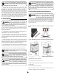
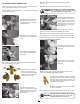
5B. Horizontal Installation (DE Only)
Multi-position coils are shipped from the factory such that they can be
installed in both vertical and horizontal applications without changes
to the coil. When installing these coils in the horizontal application,
the details mentioned in this section must be followed.
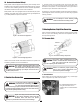
Multi-position coils come equipped with a horizontal drain pan (Plas-
tic/Metal). The plastic drain pan is protected from high temperatures
by a metal plate at the apex end of the coil.
Note: Photos are for basic illustration purposes only. Actual equip-
ment conguration may dier from that shown.
Refer to Furnace/Air Handler manufacturer literature for specic coil
installation guidelines and recommendations
.
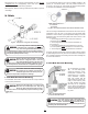
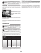
7. Metering Devices/Liquid Line Conection
Aspen coils are available with two kinds of metering devices a) ow-
rator or b) TXV. The following instructions are separated into sec-
tions by metering device.
Use Piston sizes recommended by the
outdoor unit manufacturer whenever pos-
sible. The piston should be sized accord-
ing to the capacity of the outdoor unit.
CAUTION
!
Fig 7A-1. Flowrator assembly components
Failure to install the proper piston can
lead to poor system performance and
possible compressor damage.
!
WARNING
I. Installation
I-1. Disassemble owrator body
using two wrenches and un-
screwing with a counterclockwise
motion.
Fig 5B-1. Horizontal Left Application
Fig 5B-2. Horizontal Right Application
7A. Flowrator Coils
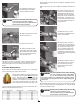
1. Ensure suction line connection joints are burr-free and clean.
Failure to do so may increase chances of a leak and introduce con-
taminants to the system. It is recommended to use a pipe cutter to
remove the spun closed end of the suction line.
Do not attempt to touch brazed joints
while hot. Severe burns may result.
!
WARNING
6. Suction Line Connection
2. Swedge (or use a eld supplied coupler) and braze the eld sup-
plied refrigerant suction line tubing to the coil stub using approved
industry practices.
Aspen coils may include a Schrader valve
on the suction manifold. Ensure that the
Schrader valve and valve core (where
present) are protected from heat to prevent leakage.
CAUTION
!
Due to higher designed radiant heat, a six
inch spacer (placed between the furnace
exit and the inlet of the evaporator) should
be installed when matching up an Aspen coil with an ultra-
low NOx (ULN) furnace.
CAUTION
!
The sensing bulb and TXV body MUST be
protected from overheating during braz-
ing. The sensing bulb and TXV body must
be covered using a quench cloth or wet cloth when brazing.
Pointing the brazing ame away from the valve and sensing
bulb provide partial protection only.
!
WARNING