Aspen HYSYS Customization Guide
Version Number: V7.3 March 2011 Copyright (c) 1981-2011 by Aspen Technology, Inc. All rights reserved. Aspen HYSYS and the aspen leaf logo are trademarks or registered trademarks of Aspen Technology, Inc., Burlington, MA. This manual is intended as a guide to using AspenTech’s software. This documentation contains AspenTech proprietary and confidential information and may not be disclosed, used, or copied without the prior consent of AspenTech or as set forth in the applicable license agreement.
Table of Contents Technical Support..................................................... v Online Technical Support Center ............................vi Phone and E-mail ................................................ vii 1 2 3 Introduction ......................................................... 1-1 1.1 Customization.................................................. 1-2 1.2 Automation & Extensibility................................. 1-3 1.3 Customizing HYSYS .....................................
5 6 7 A 4.1 Introduction .................................................... 4-3 4.2 Using the View Editor........................................ 4-8 4.3 Widget Properties............................................4-28 User Variables ...................................................... 5-1 5.1 Introduction .................................................... 5-2 5.2 Adding a User Variable...................................... 5-2 5.3 Importing/Exporting User Variables ...................
Introduction 1-1 1 Introduction 1.1 Customization ................................................................................ 2 1.2 Automation & Extensibility............................................................. 3 1.2.1 Automation ............................................................................. 3 1.2.2 Extensions .............................................................................. 4 1.3 Customizing HYSYS..................................................................
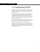
1-2 Customization 1.1 Customization Unlike its accompanying volumes, the Customization Guide does not discuss exact procedures for accomplishing tasks within HYSYS. The purpose of this volume is to demonstrate the possible simulation technologies that can be created both within HYSYS and also in addition to the application.
Introduction 1-3 be easily distributed to other machines, and they appear as any other HYSYS object in the program. You could easily develop an extension, test it, market it and sell it to other HYSYS users as a third party add-in. The Customization Guide’s purpose is threefold: • • • To introduce the user to the functionality of HYSYS automation and extensibility. To demonstrate different methods of accessing and using HYSYS objects.
1-4 Automation & Extensibility another object such as a text document. Changes to values in the spreadsheet would automatically be updated in the text document. This was a very powerful feature and was available to users without the added complexity of writing code. It was simply a matter of cutting and pasting the objects. Automation is the ability to programmatically interact with an application through objects exposed by developers of that application.
Introduction 1-5 A HYSYS extension is typically composed of two distinct and interdependent components; an ActiveX Server DLL and an Extension Definition File (EDF). The ActiveX Server DLL contains the actual code for the extensions and can be created in any OLE controller language such as Visual Basic, C++, or Delphi. Nearly any other type of compiled code base can be accessed via a short wrapper utilizing Visual Basic or C++.
1-6 Customizing HYSYS 1.3 Customizing HYSYS HYSYS can be programmatically run from any tool that supports Automation. You can set up scripts that do repetitive tasks, or you can set up programs of your own that uses HYSYS as the calculation engine. For example, the simulation of a plant can be easily hidden by a front-end created in Microsoft Excel. This front-end could be a yield prediction program of some sort that uses a rigorous simulation underneath.
Introduction 1-7 1.3.1 HYSYS & the Macro Language Editor For more information on the Macro Language Editor, consult the online help that accompanies the editor. You can find the online help in the Help menu in the Editor’s menu bar. The Macro Language Editor is accessed by selecting the Macro Language Editor command from the Tools menu in the Simulation environment. Figure 1.1 The editor is an interactive design environment for developing, testing and executing WinWrap Basic automation scripts.
1-8 Customizing HYSYS The Macro Language Editor now has two new features: • Autocompletion feature, which helps you complete the user variable codes and helps you debug the program with flyby evaluation. For example, if you want to specify “SimulationCase”, you just need to type up the first few letters of the variable, and the autocompletion feature will display all variables with similar names in a drop-down list. Figure 1.
Introduction 1-9 1.3.2 Programming HYSYS from External Programs HYSYS can be accessed from external programs using Automation. Programs such as Microsoft Visual Basic and Microsoft Excel can use HYSYS as a calculation engine, allowing you to create new applications that invisibly use HYSYS in the background. Two HYSYS objects can be created by an external program: • • The HYSYS Application object The HYSYS SimulationCase object The Application object can be created using one of the HYSYS.
1-10 Customizing HYSYS VBA Microsoft Excel and related products make use of Visual Basic for Applications (VBA). VBA is a high level programming language that is oriented around an object framework and event driven execution. Visual Basic is termed “visual” because most applications are created around a graphical interface and Visual Basic is designed to allow code associated with the interface to be added easily and intuitively.
Automation 2-1 2 Automation 2.1 Introduction................................................................................... 3 2.2 Objects .......................................................................................... 3 2.2.1 Object Hierarchy ...................................................................... 4 2.2.2 HYSYS Type Library .................................................................. 4 2.2.3 Object Browser ...............................................................
2-2 Introduction 2.1 Introduction Automation, defined in its simplest terms, is the ability to drive one application from another. For example, the developers of Product A have decided in the design phase that it would make their product more usable if they exposed Product A’s objects, thereby making it accessible to Automation. Since Products B, C and D all have the ability to connect to applications that have exposed objects, each can programmatically interact with Product A.
Automation 2-3 2.2 Objects The key to understanding Automation lies in the concept of objects. An object is a container that holds a set of related functions and variables. In Automation terminology, the functions of an object are called methods and the variables are called properties. Consider the example of a car. If it were an object, a car would have a set of properties such as: make, colour, number of doors, etc. The car object may also have methods such as: turn on, drive or open hood.
2-4 Objects tread type or model number. 2.2.1 Object Hierarchy The path that is followed to get to a specific property may involve several objects. The path and structure of objects is referred to as the object hierarchy. In Visual Basic the properties and methods of an object are accessed by hooking together the appropriate objects through a dot operator (.) function. Each dot operator in the object hierarchy is a function call.
Automation 2-5 the application by examining the type library. The HYSYS type library reveals over 340 objects that contain over 5000 combined properties and methods. For every object, the type library shows its associated properties and methods. For every property, the type library shows its return type. For every method, the type library shows what type of arguments are required and what type of value might be returned.
2-6 Objects 7. Open the View menu and select the Object Browser command (or press F2). 8. Open the Libraries/Workbooks drop-down list and select HYSYS. Navigating Through the type Library This section shows how to navigate through the type library in order to determine the object hierarchy necessary to access a particular property. Consider the desired property is the temperature of a stream called “Feed_Stream”. The first step is to begin with one of the starting objects.
Automation 2-7 type shown is not a string, Boolean, variant, double, integer, or long then it is most likely an object. The object type shown is found somewhere in the object list and is the next step to determining the object hierarchy. With prior experience in HYSYS the flowsheet object is a logical choice. Selecting the flowsheet object in the object list shows the associated properties and methods. There is an EnergyStreams property, a MaterialStreams property, and a Streams property.
2-8 Objects objects. Figure 2.4 The individual members of a collection object can be accessed by index number (like an array) or directly by name. Either approach can be used through the Item property. Examining the ProcessStream object shows a property called TemperatureValue, which is of type Double. This is the desired property. Figure 2.5 The resulting syntax for the desired property is: SimulationCase.Flowsheet.Streams. Item(“Feed_Stream”).
Automation 2-9 2.3 Automation Syntax Declaring Objects An object in Visual Basic is another type of variable and should be declared. Objects can be declared using the generic type identifier object. The preferred method however uses the type library reference to declare the object variables by an explicit object name.
2-10 Automation Syntax The example below assumes hycase is set to the SimulationCase object. Example: Set Dim hyStream As ProcessStream Set hyStream = hyCase.Flowsheet.MaterialStreams.Item(0) GetObject, CreateObject In order to begin communication between the client and server applications, an initial link to the server application must be established. In HYSYS this is accomplished through the starting objects: Application or SimulationCase.
Automation 2-11 For application objects or document objects the codes are shown below: Example: CreateObject and GetObject Set applicationobj = CreateObject(“HYSYS.Application”) or Set applicationobj = GetObject(, “PROGRAM.Application”) Set documentobj = GetObject(“c:\filepath”, “PROGRAM.Document”) In the example below, hyCase is declared as type object so it is using late binding. The hyCase variable is connected to a HYSYS case by using the GetObject function and the Set keyword.
2-12 Automation Syntax ActiveDocument property of hyApp. Example 3: Starting a HYSYS case through Automation Dim hyCase As SimulationCase Dim hyApp As HYSYS.Application Set hyApp = CreateObject(“HYSYS.Application”) hyApp.SimulationCases.Open(“c:\HYSYS\samples\c-2.hsc”) Set hyCase = hyApp.ActiveDocument Object Properties, Methods, & Hierarchy The sequence of objects is set through a special dot function. Properties and methods for an object are also accessed through the dot function.
Automation 2-13 passed when the method is called. The type library provides information about which arguments are necessary to call a particular method. A function returns a value. Sub-routines in Visual Basic do not require parentheses around the argument list. The example below, starts up HYSYS and opens a specific case. The temperature value of a specific stream is then obtained. The temperature value is obtained through a connection of three objects: SimulationCase, Flowsheet, and MaterialStreams.
2-14 Automation Syntax collection object contains a set of properties and methods for navigating and manipulating the objects in the collection. Syntax: Typical Properties of a Collections Object Item(index) Accesses a particular member of the collection by number. Index(name) Determines the index number for a member in the collection by its name. Count Returns the number of objects in the collection.
Automation 2-15 necessary to subtract one in order to access all the objects in the collection. Example 1: Accessing Collection Objects Dim Dim Set For hyStreams As Streams hyStream As ProcessStream hyStreams = hyCase.Flowsheet.MaterialStreams j = 0 To hyStreams.Count - 1 MsgBox hyStreams.Item(j).name Next j The example below, is identical to the first example except that a For Each loop is used instead of the standard For loop in order to enumerate through the Streams collection.
2-16 Automation Syntax implicitly a variant. Variants have considerably more storage associated with their use, so for a large application it is good practice to limit the number of variants being used. It is also just good programming practice to explicitly declare variables whenever possible. The dimensions of the array depend upon what property is being called. The following table lists the most common properties that return arrays and what is the dimension of the array.
Automation 2-17 property of a column. Example 2: Using Variants in HYSYS Dim hyOp As ColumnOp Dim hyStageCompFrac As Variant Set hyOp = hyCase.Flowsheet.Operations(“ColumnOp”).Item(0) hyStageCompFrac = hyOp.VapourComponentFraction For j = 0 To UBound(hyStageCompFrac,2) MsgBox “Stage “ & j +1 & “ Component 1 Vapour Fraction = “ & hyStageCompFrac(0,j) Next j The array is set to hyStageCompFrac. This array is twodimensional.
2-18 Key HYSYS Objects 2.4 Key HYSYS Objects 2.4.1 HYSYS Object Overview There are over 340 automation objects exposed in HYSYS. These objects collectively contain of over 5000 properties and methods. One of the more time consuming and difficult tasks in learning to use Automation objects is determining what objects are available and how to get at a property of interest.
Automation 2-19 accessing or opening specific simulation cases. Syntax: Connecting to the Application Set hyApp = CreateObject(“HYSYS.Application”) Syntax: Connecting to the Simulation Case Through GetObject Set hyCase = GetObject(“filepath”, “HYSYS.SimulationCase”) Through the Application Object Set hyCase = hyApp.ActiveDocument Through SimulationCases Collection Object Set hyCase = hyApp.SimulationCases.
2-20 Key HYSYS Objects Using GetObject and CreateObject The SimulationCase object and the Application object can be created directly through the GetObject function in Visual Basic. The CreateObject function can also be used to access the Application object. In general the starting object for most Automation procedures is the SimulationCase object. The example below, uses the GetObject function to start-up HYSYS with the specified case.
Automation 2-21 Starting a Particular Version of HYSYS To start a particular version of HYSYS via OLE, use one of the following HYSYS.Application ProgIDs. ProgID Description HYSYS.Application Activates the most currently registered version of HYSYS. HYSYS.Application.V7.3 Activates HYSYS V7.3 as long as it is registered. HYSYS.Application.Latest Activates the latest version of HYSYS that is registered. HYSYS.Application.
2-22 Key HYSYS Objects likewise its own property package and set of components. Subflowsheets can be accessed from the main flowsheet object through the flowsheet collection object. Syntax: Flowsheet Object Dim hyFlowsheet As Flowsheet Set hyFlowsheet = hyCase.Flowsheet The above syntax, shows how to connect to the flowsheet object of the HYSYS case. This assumes the hyCase variable is already set to the SimulationCase object in HYSYS.
Automation 2-23 2.4.3 Basis Objects The Basis objects refer predominantly to objects handled by the HYSYS BasisManager. The BasisManager object in HYSYS is responsible for handling the global aspects of a HYSYS simulation case. These objects include reactions, components, and property packages. The BasisManager object is accessed through the SimulationCase object. From the BasisManager object the FluidPackages and HypoGroups collection objects are accessed.
2-24 Key HYSYS Objects PropertyPackage object and Components object. When you access the fluid package in this way, changes can be made to the property package and the list of components. When obtaining a reference to the FluidPackage object from the flowsheet object, you are accessing the one fluid package associated with the flowsheet. You can view the property package or component list of the FluidPackage object, however you are not able to make any changes.
Automation 2-25 contains the PengRobinson property package. Example: Property Package Dim hyFluidPackages As FluidPackages Dim hyFluidPackage As FluidPackage Dim hyBasis As BasisManager Dim hyPropPackage As PropPackage Set hyBasis = hyCase.BasisManager Set hyFluidPackages = hyBasis.FluidPackages For Each hyFluidPackage In hyFluidPackages If hyFluidPackage.PropertyPackageName = “PengRobinson” Then MsgBox “PengRobinson Property Package is Present” Set hyPropPackage = hyFluidPackage.
2-26 Key HYSYS Objects counted. Example: Components Dim numComp As Integer Dim hyFluidPackage As FluidPackage Dim hyBasis As BasisManager Dim hyComponents As Components Dim hyComponent As Component Set hyBasis = hyCase.BasisManager Set hyFluidPackage = hyBasis.FluidPackages.Item(0) Set hyComponents = hyFluidPackage.Components numComp = 0 For Each hyComponent In hyComponents If hyComponent.
Automation 2-27 invoked prior to adding this hypothetical to the case. Example: HypoComponent Dim hypGroups As HypoGroups Dim hypoComp As Object hyCase.BasisManager.StartBasisChange Set hypGroups = hyCase.BasisManager.HypoGroups hypGroups.Add “myhypo” hypGroups.Item(“myhypo”).HypoComponents.Add “mycomponent”, “userhypo” Set hypoComp = hypGroups.Item(“myhypo”).HypoComponents.Item(“mycomponent*”) hypoComp.NormalBoilingPointValue = 300 hypoComp.Estimate MsgBox hypoComp.NormalBoilingPointValue hyCase.
2-28 Key HYSYS Objects Example: Accessing the Oil Manager Environment Public hyOil As OilManager hyCase.BasisManager.StartBasisChange hyCase.BasisManager.StartOilChange Set hyOil = hyCase.BasisManager.OilManager '//code to manipulate oil manager objects hyCase.BasisManager.EndOilChange hyCase.BasisManager.EndBasisChange Assays and Blends are not estimated until the EndOilChange method is invoked.
Automation 2-29 Below is an example on creating an assay. Example: Creating Assays Dim hyAssay As AssayTBP Dim hyBasis As BasisManager Set hyAssay = hyBasis.OilManager.Assays.Add(“AssayName”, “TBP”) With hyAssay .Basis = ab_LiquidVolumeFraction .BulkMolecularWeight = 300 .BulkMassDensity.SetValue 783, “API” Dim hyValue As Variant Dim hyPercent As Variant hyPercent = Array(0,10,20,30,40,50,60,70,80,90,98) hyValue = Array(26.67,123.89,176.11,221.11,275,335,399,490.56,590.56,691.67, 795.56) .
2-30 Key HYSYS Objects blend is also assigned to a stream in the HYSYS case. Example: Blends Dim hyBlend As Blend '//create blend and assign assay Set hyBlend = hyBasis.OilManager.Blends.Add(“BlendName”) hyBlend.AddAssay “AssayName” '//print out some properties Dim hyVar As Variant hyvar = hyBlend.TrueBPTemperatureValue For i = 0 To UBound(hyVar) Debug.Print hyVar(i) Next i hyBlend.InstallIntoStream “Blend_Stream” 2.4.
Automation 2-31 methods. Syntax for accessing the ProcessStream object By Name SimulationCase.Flowsheet.MaterialStreams(“streamname”) SimulationCase.Flowsheet.MaterialStreams.Item(“streamname”) By Index SimulationCase.Flowsheet.MaterialStreams.Item(j) In most instances the collection object and member object of the collection have nearly similar names. The name of the collection object is normally the member name with an “s” at the end.
2-32 Key HYSYS Objects appropriate components. Example 2: ProcessStream Dim hyFlowsheet As Flowsheet Dim hyStream As ProcessStream Dim hyComponents As Components Dim hyCompFrac As Variant Set hyFlowsheet = hyCase.Flowsheet Set hyComponents = hyCase.BasisManager.FluidPackages.Item(0).Components Set hyStream = hyFlowsheet.MaterialStreams.Item(2) hyCompFrac = hyStream.ComponentMassFractionValue For j = 0 To UBound(hyCompFrac) MsgBox “Component “ & hyComponents.
Automation 2-33 If you have specified TargetValue then specify TargetPFDif as -32767. A Petroleum Assay name (specified as szAssayName) must exist in the Petroleum Assay Manager. This assay must use the same fluid package as the stream. Example: feed.ShiftPropIFace "Arab Light", 2004, -32767, 250 The above function specifies the feed stream molecular weight (property key = 2004) as 250. This function will use the initial property of the assay “Arab Light”.
2-34 Key HYSYS Objects vtTemp1(5) = 1173.15 vtProp1(0) = 0.01 vtProp1(1) = 0.03 vtProp1(2) = 0.2 vtProp1(3) = 2 vtProp1(4) = 3 vtProp1(5) = 5 sulKey = 11029 sulBulk = 2 feed.ShiftPropCurveIFace sulKey, 6, vtTemp1, vtProp1, sulBulk In the above example, the sulfur property of the feed stream is shifted to the value 2.0. The algorithm will use 6 data points (vtTemp1 as TBP end Points and vtProp1 as Property Value).
Automation 2-35 Example: Dim x As Variant Dim intI As Integer Dim Dim Dim Dim bsCompBasisVarType As String bsTargetDistType As String vtTargetTemps(6) As Double vtTargetYields(6) As Double Dim vtTargetLEcomp(37) As Double Dim vtTargetLEcompId(37) As Double bsCompBasisVarType = "VolFrac" bsTargetDistType = "dtTBP" // these are TBP temperatures in C vtTargetTemps(0) = 100.01 vtTargetTemps(1) = 200.01 vtTargetTemps(2) = 350.
2-36 Key HYSYS Objects vtTargetLEcompId(6) = 2 ‘ Ethane vtTargetLEcompId(7) = 14 ‘ CO2 vtTargetLEcompId(8) = 15 ‘ H2S vtTargetLEcompId(9) = 55 ‘ Propene vtTargetLEcompId(10) = 3 ‘ Propane vtTargetLEcompId(11) = 4 ‘ i-Butane vtTargetLEcompId(12) = 60 ‘ i-Butene vtTargetLEcompId(13) = 56 ‘1-Butene vtTargetLEcompId(14) = 58 ‘13-Butadiene vtTargetLEcompId(15) = 5 ‘n-Pentane vtTargetLEcompId(16) = 19 ‘Water vtTargetLEcompId(17) = 273 ‘2M-1-butene vtTargetLEcompId(18) = 274 ‘3M-1-butene vtTargetLEcompId(19) = 2
Automation 2-37 in the component view as shown below: Figure 2.6 Also note that this function can only be used with HYSYS components, since Aspen Properties pure comonents have different Component IDs.
2-38 Key HYSYS Objects Property Keys Index The following is the list of property keys for commonly used properties: Figure 2.7Property Name Acidity Figure 2.
Automation Figure 2.7Property Name 2-39 Figure 2.
2-40 Key HYSYS Objects Figure 2.7Property Name Pn C7 Heptane Vol Pct Figure 2.
Automation Figure 2.7Property Name 2-41 Figure 2.
2-42 Key HYSYS Objects Figure 2.7Property Name On Vol Pct (normal) Figure 2.
Automation 2-43 flashed without interfering with the simulation case. Syntax for creating a fluid SimulationCase.Flowsheet.MaterialStreams(“streamname”).DuplicateFluid The example below, shows how to create a Fluid off of a stream and use the Fluid to perform a flash calculation. The DuplicateFluid method returns a Fluid object.
2-44 Key HYSYS Objects accessed to determine the type of phase. Syntax: FluidPhase(s) Through Collection Set hyFluidPhase = hyFluid.FluidPhases.Item(0) HeavyLiquidPhase Set hyFluidPhase = hyFluid.HeavyLiquidPhase LightLiquidPhase Set hyFluidPhase = hyFluid.LightLiquidPhase VapourPhase Set hyFluidPhase = hyFluid.VapourPhase The example below, enumerates through the FluidPhases of a Fluid and displays the phase type for each fluid in a property view.
Automation 2-45 Operations All operations have a few properties and methods in common. Operation objects contain properties for determining the feeds, products, and additional objects connected to the operation. The operation objects also contain methods for adding and removing the operations from the flowsheet and the HYSYS case. Syntax for accessing operations Getting all the operations on the flowsheet SimulationCase.Flowsheet.Operations Getting a specific collection of operations SimulationCase.
2-46 Key HYSYS Objects ColumnOp & ColumnFlowsheet The column operation is a special kind of operation in HYSYS and actually contains its own flowsheet. The ColumnFlowsheet is accessed either from the Columnop object or as a member of the flowsheets object accessed through the main flowsheet. In order to access the various temperatures, pressures, and specifications for a column the ColumnFlowsheet must be accessed. Syntax: Accessing Columns Set objColumn = SimulationCase.Flowsheet.Operations(“ColumnOp”).
Automation 2-47 value, current value, and status. Syntax: ColumnSpecification Set hyColumn = hyCase.Flowsheet.Operations(“ColumnOp”).Item(0) Set hyColumnFlowsheet = hyColumn.ColumnFlowsheet By Index: Set hyColumnSpec = hyColumnFlowsheet. Specifications.Item(0) By name: Set hyColumnSpec = hyColumnFlowsheet.Specifications.Item(“specname”) The example below, enumerates through all the column specifications and displays in a property view whether the specification is active or an estimate.
2-48 Key HYSYS Objects related to the fluids residing on a particular column stage. Syntax: ColumnStage(s) By Index: Set hyColumnStage = hyColumnFlowsheet.ColumnStages.Item(0) By Name: Set hyColumnStage = hyColumnFlowsheet.ColumnStages.Item(“1_Main TS”) Syntax: SeparationStage Set hySepStage = hyColumnStage.SeparationStage The example below, loops through each feed stage and displays in the Debug property view its molar liquid flows.
Automation 2-49 RealVariable/RealFlexVariable The RealVariable object provides additional information about a particular variable such as its units and whether it is calculated or set. HYSYS performs all calculations in SI units regardless of how the user preference settings are set. By default, the values returned through Automation are also in SI units. It becomes your responsibility to handle how units are handled when writing applications.
2-50 Key HYSYS Objects returned to variants. The presence of Flex in the object name indicates the possibility of a dynamic array (in other words, has a variable size, depending on what is being returned.) The example below, shows how to get a stream property value in a specific unit using the RealVariable method GetValue. Example 1: RealVariable Dim hyStream As ProcessStream Dim TemperatureVal As Double Set hyStream = hyCase.Flowsheet.MaterialStreams.Item(0) TemperatureVal = hyStream.Temperature.
Automation 2-51 vsDefaultedValue are integer variables specified in the type library. Fixed Attachments The FixedAttachments object is a collection object accessed from Operations or Stream objects. The FixedAttachments collection object contains a set of objects related to the feeds, products, or connected operations. Syntax: Using FixedAttachments Set FixAtch = SimulationCase.Flowsheet.Operations.Item(0).AttachedFeeds Set hyStream = FixAttachObj.
2-52 Key HYSYS Objects Solver & Integrator The Solver is accessed from the SimulationCase object. The Solver object can be used to turn the calculations on and off. Syntax for the Solver and Integrator Solver SimulationCase.Solver.CanSolve = False SimulationCase.Solver.CanSolve = True Integrator SimulationCase.Solver.Integrator.Active = True SimulationCase.Solver.Integrator.
Automation 2-53 SpreadsheetOp & SpreadsheetCell(s) The SpreadsheetCells object is a collection of SpreadsheetCell objects. The cell properties allow access to information related to the HYSYS variable being imported or exported, the formulas associated with the cell, and the value within the cell. Syntax: SpreadsheetOp and SpreadsheetCell(s) Set hySS = hyCase.Flowsheet.Operations.Item(“spreadsheetname”) Set hyCell = hySS.
2-54 Key HYSYS Objects 2.4.8 PFD Objects PFD objects are used for the manipulation and automation of PFDItems. A PFDItem is any item that is found on the HYSYS PFD, such as a unit op or a stream. You can use PFD objects to Move, Size, Mirror, Rotate, Hide, etc. any PFDItem. PFD objects also allow you to import and display a selection of PFDItems in to Visio, a CAD application or Excel (what items you get depends on what parameters you specify).
Automation 2-55 2.5 Example 1: The Macro Language Editor In this example, you use the HYSYS Macro Language Editor to build a macro tool that displays the Mach number for a selected stream over a number of different pipe sizes. The speed of sound in the stream fluid also appears. The fluid velocity calculated for each pipe size is the average fluid velocity; no attempt is made to estimate the maximum velocity.
2-56 Example 1: The Macro Language 2. Add a function that returns the Stream object that you choose from a list. Creating separate functions allows for easy re-use in other programs. Code Explanation Function SelectStream(simcase As Object) As Object Signifies the beginning of the SelectStream function. This function takes a SimulationCase object and prompts the user to select a Stream from a list of streams in the case, returning an interface to the Stream. Set FS = simcase.
Automation 2-57 3. At this time it is probably a good idea to globally declare some constants that are used in the Main sub-routine as shown below. Figure 2.10 4. You can now begin defining the Main sub-routine. Enter the following code: Code Explanation Sub Main Signifies the beginning main sub-routine. pipeSizes(1) pipeSizes(2) pipeSizes(3) pipeSizes(4) pipeSizes(5) pipeSizes(6) pipeSizes(7) pipeSizes(8) = = = = = = = = 2 3 4 6 8 10 12 16 Defines an array of pipe sizes (in inches).
2-58 Example 1: The Macro Language Code Explanation Set flow = strm.MassFlow If flow.IsKnown Then flowValue = flow.GetValue(“lb/hr”) flowValue = flowValue / 3600 Else GoTo NoFlow End If Check to see if the selected stream has a defined mass flow rate. If the flow rate is known, convert the flow rate in to “lb/s”. Set rho = strm.MassDensity If rho.IsKnown Then rhoValue = rho.GetValue(“lb/ft3”) Else GoTo NoRho End If Checks to see if the stream’s mass density has been calculated.
Automation Code 2-59 Explanation For num = 1 To nPipes rSquared = pipeSizes(num) * pipeSizes(num)/144.0/ 4.0 Mach = flowValue / pi / rSquared / soundVel sizetxt = Format(pipeSizes(num), "###,###,###.###") Machtxt = Format(Mach, "###,###,###.#####") DispText(num + 1) = Format$(sizetxt, "@@@@@@@@@@@@@@@") + " " + Format$(Machtxt, "@@@@@@@@@@@@@@@") Next num For each pipe size, the Mach number is calculated, formatted and stored in the previously created array of strings.
2-60 Example 1: The Macro Language 5. Once you have finished adding this code, you should be ready to run the program. First ensure that HYSYS has a case loaded with at least one fully defined stream. You can start the program using one of the following ways: • Start/Resume icon Right-click on any area of the Macro Language Editor property view, select Macro | Run command from the Object Inspect menu. • Pressing the F5 on the keyboard. • Clicking the Start/Resume icon on the toolbar.
Automation 2-61 7. Be sure to save the program by doing one of the following: • • • Right-click on any area of the Macro Language Editor property view, select File | Save from the Object Inspect menu. Press the CTRL S hot key combination. Clicking the Save icon in the toolbar.
2-62 Example 2: Automation in Visual 2.6 Example 2: Automation in Visual Basic In this example HYSYS is used as the Automation server for a unit conversion program. More specifically, you are accessing an object called the UnitConversionManager which manages unit conversion within HYSYS. Although Visual Basic 5.0 is recommended for this example, you can create this Automation application in Visual Basic Editor provided in MS Excel 97® and MS Word 97®.
Automation 2-63 Your screen should appear similar to the figure below. Figure 2.13 Toolbox Form Properties Tiled property view 2. By default you should have a form associated with the project. Begin, by giving the form a name. In the Name field of the Properties tiled property view give the form the name: frmUCSM. 3. In the Caption field type: UNIT CONVERSION MANAGER. This caption should now appear in the Title Bar of the form. 4.
2-64 Example 2: Automation in Visual 5. From the toolbox select the Combo Box icon and create a combo box on the form as shown below. Combo Box icon Figure 2.14 6. Ensure that the combo box is the active control. This can be done in one of two ways: • Select the combo box on the form so that the object guides appear around the object. • From the drop-down list found at the top of the Properties tiled property view select the name of the combo box you have just created. 7.
Automation 2-65 10. Now add an Text Box next to the Combo Box you created. Use the method described in Steps #6 - #7 to name this Text Box ebFromValue. Repeat Steps #8 - #9 to add a Label above the ebFromValue Text Box that reads From Value. Figure 2.16 11. Add the following objects to the property view using the previously described methods. Figure 2.
2-66 Example 2: Automation in Visual 12. Only two more objects are required on the form. Select the Command icon control from the toolbox and add two buttons to the property view as shown below. Command icon Figure 2.18 Object Type - Command icon Object Type - Command icon Name - btConvert Name - btExit Caption - Convert Caption - Exit 13. You are now ready to begin defining the events behind the form and objects.
Automation 2-67 The following property view should appear: Figure 2.19 The Private Sub Form_Load() method definition is only visible if you enter the code environment by double-clicking the form. 14. Begin by declaring the following variables under the Option Explicit declaration. Figure 2.20 If you attempt to use an undeclared variable, an error occurs at compile time.
2-68 Example 2: Automation in Visual 15. The first sub-routine should already be declared. The Form_Load sub-routine is the first sub-routine called once the program is run. It is usually used to initialize the variables and objects used by the program. Enter the following code in to the Form_Load sub-routine. Code Explanation Private Sub Form_Load() Signifies the Start of the form load sub-routine. You do not have to add it as it should already be there. ddUnitSet.Clear ddFromUnit.Clear ddToUnit.
Automation Code 2-69 Explanation Clears any text that appears in the lbToValue label. lbToValue.Caption = "" End Sub Signifies the end of the sub-routine. This line does not need to be added. 17. The next 2 sub-routines reset the lbToValue label whenever an option is selected in either the ddFromUnit or ddToUnit combo box. Code Explanation Private Sub ddFromUnit_Click() Signifies the Start of the sub-routine. Clears any text that appears in the lbToValue label. lbToValue.
2-70 Example 2: Automation in Visual Code Explanation Intermediate = FromUC.ToCalculationUnit(FromValue) ToValue = ToUC.FromCalculationUnit(Intermediate) lbToValue.Caption = CStr(ToValue) Converts the contents of the ddFromValue combo box from the FromUC units to HYSYS internal units (Intermediate). It then converts the Intermediate value from internal units to the ToUC units. It then displays the converted value in the lbToValue label. End Sub Signifies the end of the sub-routine.
Extensibility 3-1 3 Extensibility 3.1 Introduction................................................................................... 3 3.2 Implementing Interfaces ............................................................... 5 3.2.1 Implementing an Interface Through a Dispatch Interface............... 5 3.2.2 Implementing an Interface Through a Custom Interface ................ 6 3.3 Data Types ..................................................................................... 6 3.
3-2 Extensibility 3.9.2 ExtnPropertyPackage Interface .................................................51 3.10 Extension Unit Operations ..........................................................52 3.10.1 ExtnUnitOperationContainer Interface....................................53 3.10.2 ExtnUnitOperation Interface .................................................54 3.10.3 Passes...............................................................................54 3.11 Extension Transition Objects ..............
Extensibility 3-3 3.1 Introduction HYSYS provides the unique capability of enhancing its functionality through the addition of custom objects to a simulation. With its open concept, the functionality of HYSYS can be extended to include your unique or proprietary calculations. Currently, you can add: • • • Extension Unit Operations Extension Reaction Kinetics Extension Property Packages Extensions are packaged in to two distinct files making them easy to transfer to different machines.
3-4 Introduction Figure 3.1 HYSYS Container Extension Code HYSYS finds extensions by looking for specific keys in the System Registry. When an extension is registered on a computer, information about it is added to the Registry. Upon start-up, HYSYS scans the Registry for this information, and adds user-specified descriptions to the appropriate lists within the program. For instance, when a unit operation extension is created with the description provided as “MY Unit Op”.
Extensibility 3-5 3.2 Implementing Interfaces An extension implements an interface if it supports the methods in that interface. There are two different ways of implementing an interface. 3.2.1 Implementing an Interface Through a Dispatch Interface An extension can implement interfaces through Dispatch interfaces. This can be done in Visual Basic if the extension is implemented as a Visual Basic Class.
3-6 Data Types 3.2.2 Implementing an Interface Through a Custom Interface An extension can also be implemented by overloading the Custom interfaces defined for the extension. For example, an extension Unit Operation can be created by overloading the ExtensionObject interface and the ExtnUnitOperation interface. When an extension is created in this manner, all methods of the interface must be overloaded (this is a requirement of the C++ language definition).
Extensibility 3-7 When sending an array of numbers to HYSYS they should always be of type REAL or LONG. 3.4 Extension Development Kit A number of tools are provided in the HYSYS Extension Development Kit. These tools are not required to build extensions for HYSYS, but they make the job much easier. Included in the kit are the following: File Description hysys.
3-8 Extension Development Kit File Description The HYSYS View Editor Allows you to: • Define extension information for the registration program. • Define Variables for HYSYS to create and manage on behalf of an extension. • Create property views for an extension. Aspentech. HYSYS.Interop. dll The HYSYS Interop Assembly contains .NET definitions for all objects exposed by HYSYS as well as definitions for interfaces required by HYSYS Extensions. .
Extensibility 3-9 3.5 Creating an Extension 3.5.1 In Visual Basic Creating an extension in Visual Basic is a very straightforward procedure. The following six steps can be used as a general framework: 1. Create the Extension Definition. 2. Create the Object property views. 3. Implement the Required Methods. 4. Register the Extension. 5. Debug the Extension. 6. Distribute the Extension. These steps are explained in more detail in the following sections.
3-10 Creating an Extension It is possible to create an EDF with 0 views. For more information on the View Editor see Chapter 4 - Extension View Editor. Once the preliminary definition information is provided, you specify the variables that the object owns and that are visible to the user. These variables are of the following types: Variable Type Description Numeric • Represent numerical quantities and have a Variable Type that allows HYSYS to manage Unit Conversions for the user.
Extensibility 3-11 Each DefaultView form must have a unique name. The object’s default property view must be called DefaultView as it is the property view HYSYS attempts to open when the object is instantiated, provided the functionality of the OnView method is not overridden. Implement the Required Methods To implement an extension from Visual Basic, you must create a project containing a Class Module. This Class Module must implement whatever methods are required by the container.
3-12 Creating an Extension Debug the Extension For more information on debugging, please consult your Visual Basic manual and help files. To debug the extension, you can set breakpoints on just about any line in your Visual Basic class. Initially, you should probably set a breakpoint on the Initialize method. Then, start the extension (via the Start button or the Start command in the Run menu). Next, start HYSYS and create an instance of your extension.
Extensibility 3-13 3.5.2 In C++ The following six steps provide a framework for creating an extension in C++: 1. Create the Extension Definition. 2. Implement the Required Interfaces. 3. Implement the ClassFactory. 4. Create and Register the DLL. 5. Debug the Extension. 6. Distribute the Extension. These steps are explained in more detail in the following sections.
3-14 Creating an Extension For more information on the View Editor see Chapter 4 - Extension View Editor. Once the preliminary definition information is provided, you specify the variables that the object owns and that is visible to the user. These variables are of the following types: Variable Type Description Numeric • Represent numerical quantities and have a Variable Type that allows HYSYS to manage Unit Conversions for the user. • May have zero, one, or two dimensions.
Extensibility 3-15 Definitions of the interfaces that you must implement (as well as any interfaces provided by HYSYS objects) are provided in the hysys.hh file, that is included in the Extension Development Kit. You must include this file in any source files that access the defined interfaces. Implement the Class Factory When HYSYS creates an instance of your extension object, it accesses the COM Library which calls the function DllGetClassObject which is contained in the DLL.
3-16 Creating an Extension Create & Register the DLL When you build your project, you must implement it as a 32-bit Dynamic Link Library (DLL). This DLL must contain code for your extension, a ClassFactory to create your extensions, and a DllRegisterServer entry point. The Extension Development Kit provides extsdk.cpp, which contains a ClassFactory and an implementation of DllRegisterServer. If you use this ClassFactory, you must include this file in your project.
Extensibility 3-17 To distribute your extension, you must provide the DLL file, the EDF file, and any other files required by your extension (i.e., a separate FORTRAN DLL called from you extension). You must register your extension on each individual machine that uses the extension calculations. You can use the registration tool found on the Extensions tab of the Session Preferences property view for this, or you can include this step in your own setup program. 3.5.3 In C# or VB.
3-18 Creating an Extension property views. The selection of the ProgID is explained in the following sub-section entitled: Register the Extension. It is possible to create an EDF with 0 views. Once the preliminary definition information is provided, you specify the variables that the object owns and that are visible to the user.
Extensibility 3-19 variable with the widget. A widget is an equivalent term for a control. Each DefaultView form must have a unique name. The object’s default property view must be called DefaultView as it is the property view HYSYS attempts to open when the object is instantiated, provided the functionality of the OnView method is not overridden. Implement the Required Methods To implement an extension in C# or VB.NET, you must first create a Class Library project.
3-20 Creating an Extension Debug the Extension To debug the extension, you can set breakpoints on just about any line in your class. Initially, you should probably set a breakpoint on the Initialize method. Then, set HYSYS.exe as the external program in the Project Properties Debug page. You can debug your extension in Microsoft Visual Studio 2003 or 2005 by setting breakpoints in the code and by attaching to running copy of HYSYS from the Attach to Process dialog from the Tool menu.
Extensibility 3-21 proprietary information or methods. To distribute your extension, you must provide the DLL file, the EDF file, and any other files required by your extension (i.e., a separate FORTRAN DLL called from you extension). You must register your extension on each individual machine that uses the extension calculations. You can use the registration tool found on the Extensions tab of the Session Preferences property view for this, or you can include this step in your own setup program. 3.
3-22 Registering Extensions Extension Definition File for the object. The type of the extension is given by the ExtensionType entry. The type can be UnitOperation, PropertyPackage or KineticReaction. The class descriptor is optional, and currently is ignored if present. 3.6.1 Registering Extensions Written in C++ When you create an extension in C++, you must implement a DllRegisterServer function in the DLL containing the extension. This function is called from HYSYS when registering the extension.
Extensibility 3-23 3. Use the File Path group to find the directory in which the DLL file is saved. Once you find the DLL file, select it and click the OK button. Figure 3.2 The Extensions tab should now appear similar to the figure below. Figure 3.3 You are now ready to use the extension in HYSYS.
3-24 Registering Extensions 3.6.2 Registering Extensions Written in Visual Basic Refer to Section 3.6.1 Registering Extensions Written in C++, for the step by step procedure for registering HYSYS extensions. Extensions written in Visual Basic may be run from within Visual Basic, or may be compiled to an ActiveX DLL file. Either way, Visual Basic takes care of registering half of the information required for HYSYS to find the extension.
Extensibility 3-25 3.6.3 Registering Extensions Written in C# or VB.NET To register an extension written in C# or VB.NET, use the following procedure: 1. Start HYSYS. From the Tools menu, select Preferences command. The Session Preferences property view opens. 2. Go to the Extensions tab and click the Register an Extension button. This opens the Select an Extension to be Registered property view. 3. Use the File Path group to find the directory in which the DLL file is saved.
3-26 Extension Interface Details below. Figure 3.5 You are now ready to use the extension in HYSYS. 3.7 Extension Interface Details Three types of extensions can currently be created for use within HYSYS: • • • Unit Operations Kinetic Reactions Property Packages Each extension type is associated with a unique container interface derived from the ExtnContainer object. For instance Unit Operation Extensions have an ExtnUnitOperation interface. 3.7.
Extensibility 3-27 and properties for the extension.
3-28 Extension Reaction Kinetics 3.7.2 ExtensionObject Interface Every extension must implement the ExtensionObject interface. This interface defines methods that are common to all HYSYS extensions. No methods in this interface are mandatory; that is, all methods may be ignored if the extension does not implement them. Derived from Properties IDispatch none Methods • • • • • • OnHelp Save StatusQuery Terminate VariableChanged VariableChanging 3.
Extensibility 3-29 These previously described interfaces allow a reaction to be implemented and associated with a HYSYS case through a fluid package. The Reaction Extension also requires the definition of two methods in order for the extension to be viable: Method Description Details Initialize The Initialize method is called whenever the extension is first added or whenever a case containing the extension is reopened.
3-30 Extension Reaction Kinetics Extension Definition Files An extension definition file is required for the kinetic reaction extension. Since HYSYS uses a specific interface for reaction extensions, the property view within the EDF is not the primary property view when the extension is accessed in HYSYS. If you do create a customized property view in the View Editor, you can access it through the View Extension Parameters button found on the Parameters tab. Figure 3.6 3.8.
Extensibility 3-31 3.8.2 ExtnKineticReactionCont ainer Interface The ExtnKineticReactionContainer interface is passed to an extension Kinetic Reaction in its Initialize method. Derived from ExtnContainer Properties • • • • • • • • BaseReactant BasisConversion MaxTemperature MinTemperature Phase RateConversion Reactants ReactionBasis Methods • AddReactantProperty • RemoveReactantProperty • SetReactionPropertyState 3.8.3 Kinetic Reaction Example In this example, you use Visual Basic 5.
3-32 Extension Reaction Kinetics 3. Make sure that the HYSYS 3.* Type Library checkbox is selected in the References property view, which is accessed by selecting the References command from the Project menu. Figure 3.7 4. In the Properties tiled property view, ensure that the Instancing drop-down list is set to 5-MultiUse. 5. In the Properties tiled property view, rename the class module VinylAc. 6. Save the class and project by selecting Save Project command from the File menu.
Extensibility 3-33 8. The first function declared is the Initialize function. It is called when the extension is first added to HYSYS or when a case containing the extension is loaded. Code Explanation Public Function Initialize(ByVal Container As Object, ByVal IsRecalling As Boolean) As Long Initialize is called when the extension is first added to the simulation or when a simulation case containing the extension is loaded. On Error GoTo ErrorTrap Enable Error trapping.
3-34 Extension Reaction Kinetics Code Explanation Set hyReactant = hyContainer.Reactants.Add("AceticAcid") hyReactant.StoichiometricCoefficientValue = -1 Set hyReactant = hyContainer.Reactants.Add("Oxygen") hyReactant.StoichiometricCoefficientValue = -0.5 Set hyReactant = hyContainer.Reactants.Add("VinylAcetate") hyReactant.StoichiometricCoefficientValue = 1 Set hyReactant = hyContainer.Reactants.Add("H2O") hyReactant.StoichiometricCoefficientValue = 1 hyContainer.
Extensibility 3-35 9. The other function that is required to implement a kinetic reaction extension is the ReactionRate function. Code Explanation Public Function ReactionRate(ByVal Fluid As Object, ByVal RxnTemperatureInC As Double, ByVal RxnVolumeInKmolPerM3 As Double, rate As Double) As Boolean This function is called whenever the extension is executed. On Error GoTo ErrorTrap Enable Error trapping. Dim Dim Dim Dim Dim Dim Dim Dim Dim Dim Dim Declare local variables.
3-36 Extension Reaction Kinetics Code Explanation rate = 0.1036 * Exp(-3674 / RxnTemperatureinK) * OxygenPP * EthylenePP * AceticAcidPP * (1 + 1.7 * WaterPP) / ((1 + 0.583 * OxygenPP * (1 + 1.7 * WaterPP)) * (1 + 6.8 * AceticAcidPP)) * hyBulkDens.Value * 1000 Calculate the reaction rate1. The rate is in g mol AceticAcid consumed/min-g catalyst. hyBulkDens.Value is multiplied by 1000 to convert it to g catalyst/m3 reactor volume.
Extensibility 3-37 Creating the Extension Definition File (EDF) In order to complete the Kinetic Reaction Extension, you must create an EDF. This is done through the Extension View Editor. For more information on installing and accessing the View Editor, see Section 4.1.1 Accessing the View Editor. New File icon If it has been installed, the Extension View Editor is found in the same launch point in the Start menu as HYSYS. 1.
3-38 Extension Reaction Kinetics 5. Select Kinetic Reaction as extension type in the Type dropdown list. 6. Specify the information in the Variables of Selected Object group as shown below, and select the Persistent checkbox. Figure 3.10 7. Click the Close button. This returns you to the Views Manager property view. Figure 3.
Extensibility 3-39 8. From the Existing Views list, select the DefaultView and click the Edit button. The DefaultView form appears. It consists of several default objects that are not used in this example. These objects have to be deleted. 9. Begin by deleting the Page Tabs widget. Select the tabs found at the bottom of the DefaultView form as shown below and press the DELETE key. Figure 3.12 Static Text Text Entry Page Tabs 10.
3-40 Extension Reaction Kinetics Adding Widgets to the DefaultView form 1. From the Widgets Palette select a Numerical Input widget. 2. Right-click, hold, and drag the widget into the DefaultView form. 3. When you find an appropriate part of the property view to place the widget, release the mouse button and the widget should drop into place. Use the drag and drop method described in the above steps to add the two Static Text widgets and a Button widget as shown below. Figure 3.14 4.
Extensibility 3-41 5. For the upper Static Text widget specify properties as shown below. When you are finished click the OK button. Figure 3.15 6. For the lower Static Text widget specify properties as shown below. When you are finished click the OK button. Figure 3.
3-42 Extension Reaction Kinetics 7. For the Numerical Input widget specify properties as shown below. When you are finished click the OK button. Figure 3.17 The Target Moniker field is specified by clicking the Ellipsis icon associated with the field and selecting Bulk Density from the Select Number Variable property view. 8. Open the Properties property view of the Button widget. 9.
Extensibility 3-43 11. Click the Insert button on the Edit Messages property view. The Select Message property view appears. Select the Close the View message from the list. Figure 3.18 12. Click the OK button to add this message to this button. The Edit Messages property view appears as shown below. Figure 3.19 13. Click the OK button on the Edit Messages property view to close this property view and return to the Button Properties property view.
3-44 Extension Reaction Kinetics 14. Specify the Name field as shown below. When you are finished click the OK button. Figure 3.20 The property view now appears as shown below. Figure 3.21 15. Select Save command from the File menu and save the EDF file as “VinylAc.edf” in the same directory as the DLL file. Attaching the Extension to HYSYS You are now ready to attach the extension to HYSYS. The following steps demonstrate how to attach an extension within HYSYS. 1. Start HYSYS.
Extensibility 3-45 3. Use the File Path group to find the directory in which the VinylAc.dll file is saved in. Once you find the DLL file, select it and click the OK button. Figure 3.22 4. The HYSYS Extension Registration property view appears and displays whether the registration was successful or not. Click the OK button to close the property view. The Extensions tab should now appear similar to the figure below. Figure 3.
3-46 Extension Property Packages 5. You can now go to the Reactions tab of the Simulation Basis Manager property view and add a VinylAcetate Reaction Extension from the Reactions property view. Figure 3.24 3.9 Extension Property Packages You can put your own physical property calculations into HYSYS as an Extension Property Package, which appears to the user as any other property package in the program. HYSYS makes calls to property packages under a number of different situations.
Extensibility 3-47 The ExtnPropertyPackage interface is not a dual interface; for efficiency, non-ActiveX Automation compatible data types are passed as parameters. This means that Extension Property Packages cannot be easily written in Visual Basic, and cannot be implemented as Local Servers. Initialization When an Extension Property Package is initialized, it must fill in the ExtensionPPkgInit structure passed to it by its container.
3-48 Extension Property Packages has returned a non-zero for NumberOfPreselectedComponents), the container handles the implementation of the IsComponentAllowed method, allowing the extension developer to return E_NOTIMPL for the method. If the property package cannot handle changes to the component slate, the CanExchangeComponents flag can be set in the ExtensionPPkgInit structure. If this flag has been set, HYSYS only allows you to add or remove components from the end of the list.
Extensibility 3-49 Data Member Details IsActivityModelType This should be set to True if the property package can be considered an activity model property package. A number of flash algorithms in HYSYS optimize their algorithms based on the value of this data member. CanExchangeComponents This member should be set to True if the property package can handle changes to the location of components in the component slate.
3-50 Extension Property Packages 3.9.1 ExtnPPkgContainer Interface The ExtnPPkgContainer interface is passed to an Extension Property Package in its Initialize method.
Extensibility 3-51 3.9.2 ExtnPropertyPackage Interface The ExtnPropertyPackage interface must be implemented by all Extension Property Packages. Only the Initialize method must be supported, all others could return E_NOTIMPL.
3-52 Extension Unit Operations 3.10 Extension Unit Operations You can implement Unit Operation calculations in HYSYS by creating an Extension Unit Operation. To implement an Extension Unit Operation, you must implement two interfaces: Interface Description ExtensionObject Called when unit operation extension is added to the simulation. ExtnUnitOperation Called when the unit operation extension is used. These objects allow the unit operation to function in the HYSYS environment.
Extensibility 3-53 Method Description Execute Extension Unit Operations perform their calculations within their Execute method. This method is called by the Steady State Solver during the Execute Passes; it must not be called directly by the extension. The Execute method is called whenever a stream connected to the extension is changed or when any of the variables marked as trigger solve in the EDF are changed. HYSYS automatically calls the Execute method and pass the Forgetting argument.
3-54 Extension Unit Operations 3.10.2 ExtnUnitOperation Interface The ExtnUnitOperation interface must be implemented by all Extension Unit Operations. Only two methods (the Initialize method and the Execute method) are mandatory. Derived from Properties IDispatch none Methods • BasisChanged • Execute • Initialize 3.10.3 Passes Execute Passes The Solver performs steady state calculations in two passes: the Forget Pass and the Calculate Pass.
Extensibility 3-55 condition occurs. When this happens, the Solver stops and switches in to Hold Mode. To allow different objects to calculate different values because of changes in the flowsheet, it is necessary that values that depend on another changing value be forgotten. This forgetting occurs during the Forget Pass. Forget Pass When the value of a variable changes, the Solver first does one Solve Pass on the flowsheet with the value marked as unknown.
3-56 Extension Unit Operations The Execute method of an object can be called more than once in either of the Solve Passes, as variables in the object are touched by other objects in the flowsheet. 3.10.4 Extension Unit Operation Example In this example, you use Visual Basic 5.0 to build a unit operation extension that saturates a feed stream with Water. 1. Open a new project in Visual Basic 5.0 and from the New tab of the New Project property view select the ActiveX.DLL icon and click the Open button.
Extensibility 3-57 4. Rename the project name to UnitOpExtn as shown. Figure 3.26 5. Save the class and project by selecting Save Project command from the File menu. Save the class and project as Saturate.cls and Saturate.vbp. 6. Begin by defining the global variables in the Project Code Editor: Code Explanation Option Explicit Used to force explicit declaration of all variables in that module. Declare the global HYSYS objects. The hy prefix is a convention to identify variables which come from HYSYS.
3-58 Extension Unit Operations Code Explanation Dim H2O As Integer • The index for water. Dim Temp As Variant • Temporary variable. Dim MoleFl As Variant • Array of molar flows. Dim Count As Integer • Count variable. Dim i As Integer • Count variable. Dim IsKnownFeedArray As Variant • Are the feed streams in the array valid. Dim CalcError(0 to 1) As Boolean • Error level used to display status messages. Dim IsIgnoredBool As Boolean • Indicates if the unit op is ignored.
Extensibility Code 3-59 Explanation Set hyFeedStrm = hyContainer.FindVariable("FeedStream").Varia ble.object Set hyProdStrm = hyContainer.FindVariable("ProductStream").Va riable.object Set hyWatStrm = hyContainer.FindVariable("WaterStream").Vari able.object Set an object reference to the Feed, Product and Water stream attachment objects in the EDF.
3-60 Extension Unit Operations Code Explanation Set Components = hyContainer.Flowsheet.FluidPackage.Component s WaterPresent = False For Each Component In Components If Component.Name = "H2O" Then WaterPresent = True Next Component If Not WaterPresent Then GoTo ErrorTrap H2O = Components.Index("H2O") Determine if water is present (ensure it hasn't been removed). Get the index for water. Set hyFeedStrm = hyContainer.FindVariable("FeedStream").Varia ble.object Set hyProdStrm = hyContainer.
Extensibility Code 3-61 Explanation WorkFluid.TPFlash hyFeedStrm.TemperatureValue, hyFeedStrm.PressureValue If WorkFluid.FluidPhases.Count = 1 Then CalcError(0) = True GoTo ErrorTrap End If Do a TP Flash on the fluid at the temperature and pressure of the stream hyFeedStrm. If there is a second phase then an error has occurred. Temp = hyWatStrm.ComponentMolarFraction If Temp(0) = conEmpty Then MoleFl = hyWatStrm.
3-62 Extension Unit Operations Code Explanation Do While WorkFluid.FluidPhases.Count = 1 Count = Count + 1 Set WorkFluid = hyFeedStrm.DuplicateFluid WatFluid.MolarFlowValue = WorkFluid.MolarFlowValue * (Count / 20) WorkFluid.AddFluid WatFluid WorkFluid.TPFlash hyFeedStrm.TemperatureValue, hyFeedStrm.PressureValue Loop Determine water stream flow required to saturate feed stream. MoleFl = WorkFluid.HeavyLiquidPhase.
Extensibility Code 3-63 Explanation hyContainer.SolveComplete This line prevents a second Calculation pass, because it is not required. See the comment associated with the If Not Forgetting Then line of code at the beginning of the code. Read the section on the SolveComplete method in Extending HYSYS Help file for more information. CalcError(0) = False CalcError(1) = False End If Reset error flags. ErrorTrap: Line to which the On Error statement branches if an error occurs.
3-64 Extension Unit Operations Code Explanation If hyWatStrm Is Nothing Then Call hyStatus.AddStatusCondition(slMissingRequire dInformation, 4, "Water Stream Required") OK = False End If If there is no water stream attached to the unit op, an error message appears telling you that a water stream is required. If hyProdStrm Is Nothing Then Call hyStatus.
Extensibility Code 3-65 Explanation IsKnownFeedArray = hyFeedStrm.ComponentMolarFraction.IsKnown If Not IsKnownFeedArray(0) Then Call hyStatus.AddStatusCondition(slMissingOptiona lInformation, 8, "Unknown Feed Composition") OK = False End If Check to see if the feed stream’s composition has been set. If it has not, an error message is sent to the status bar indicating an Unknown Feed Composition. If CalcError(0) Then Call hyStatus.
3-66 Extension Unit Operations The default View Editor should appear as shown below: Figure 3.27 The file path in the View File group may be different, depending on where you installed HYSYS. Objects Manager icon 2. Click the Objects Manager icon to view the Objects Manager property view. 3. In the ProgID/CLSID cell enter UnitOpExtn.Saturate as the extension ID. 4. Enter an appropriate description for the extension in the Description cell, such as Saturate Extension. 5.
Extensibility 3-67 The Object Manager property view now appears similar to the figure below. Figure 3.28 7. Click the Close button. This returns you to the Views Manager property view. Figure 3.
3-68 Extension Unit Operations 8. From the Existing Views list, select DefaultView and click the Edit button. The DefaultView form appears. Figure 3.30 Defining the Tabs 1. To open the Properties property view of the Page Tabs widget (or for any widget), do one of the following: • Double-click on the widget • Right-click the widget and select Properties command from the Object Inspect menu, where Widget Type would be Button for a Button widget. 2.
Extensibility 3-69 3. The Select Number Variable property view appears. From the list select Current Page and click the OK button. Figure 3.31 4. In the Label field of the Static Tabs group change the two entries Page1 and Page2 to Connections and Worksheet, respectively. Figure 3.32 5. Close the Page Tabs Properties property view by clicking the OK button. 6. Now controls must be added to the tabs.
3-70 Extension Unit Operations 7. A default controller has already been set up for the page tabs called PageController. Click the Edit button to view the Visibility Controller Properties property view. 8. In the States matrix, you should notice two entries: Page1 and Page2. Rename these two states Connections and Worksheet, respectively, to coordinate the states to respective tab names. Figure 3.33 9. Click the OK button to return to the Visibility Manager property view.
Extensibility 3-71 3. Place a Static Text widget above each Attachment Name widget. Figure 3.34 4. First the Feed widgets (i.e., the Attachment Name and Static Text widget on the left) is defined. For the Feed Static Text widget specify properties as shown below. When you are finished click the OK button. Figure 3.
3-72 Extension Unit Operations 5. For the Feed Attachment Name widget specify properties as shown below. When you are finished click the OK button. Figure 3.36 The Target Moniker field is specified by clicking the Ellipsis icon associated with the field and selecting FeedStrm from the Select Attachment property view. 6. For the Water Stream Static Text widget specify properties as shown below. When you are finished click the OK button. Figure 3.
Extensibility 3-73 7. For the Water Attachment Name widget specify properties as shown below. When you are finished click the OK button. Figure 3.38 The Target Moniker field is specified by clicking the Ellipsis icon associated with the field and selecting WaterStrm from the Select Attachment property view. 8. For the Product Stream Static Text widget specify properties as shown below. When you are finished click the OK button. Figure 3.
3-74 Extension Unit Operations 9. For the Product Attachment Name widget specify properties as shown below. When you are finished click the OK button. Figure 3.40 The Target Moniker field is specified by clicking the Ellipsis icon associated with the field and selecting ProductStrm from the Select Attachment property view. The DefaultView form now appears as shown in the figure below. Figure 3.
Extensibility 3-75 Adding Widgets to Worksheet Tab The next step is to add widgets to the Worksheet tab on the DefaultView form. 1. In the Visibility Manager property view, select the Worksheet radio button. To open the Visibility Manager property view, right-click the DefaultView form background and select Open Visibility Manager command from the Object Inspect menu. 2. Insert a Matrix widget on the Worksheet tab. Resize the widget so that about 1 cm space appears between the matrix and tab borders.
3-76 Extension Unit Operations 6. Select the Vertical Direction checkbox. The Matrix Properties property view should appear similar to the figure below. Figure 3.43 7. The Data Set list should contain a default data set. Click the Insert button to open the Select a Data Type property view and add a new data set to the list. 8. On the Select a Data Type property view, select Text as the data type and click the OK button. Figure 3.44 9. A Text Data Set Properties property view appears.
Extensibility 3-77 12. From the list select Object Name as shown in the figure below and click the OK button. Figure 3.45 13. The Select Text Variable property view closes, and you are returned to the Text Data Set Properties property view. 14. In the Label group enter Name as the label associated with field and click the OK button to close the Data Set Properties property view. Figure 3.46 15. Insert a Numeric data set as described in the above steps #7 and #8. 16.
3-78 Extension Unit Operations 19. From the list select Molar Flow and click the OK button. The Select Number Variable property view closes, and you are returned to the Numeric Data Set Properties property view. 20. In the Label group enter Molar Flow as the label associated with field and click the OK button to close the Numeric Data Set Properties property view. Figure 3.47 21. Click the OK button on the Matrix Properties property view to close the property view.
Extensibility 3-79 the only two cells defined. 22. Select Save command from the File menu and save the EDF as Saturate.edf in the same directory as the DLL file. Attaching the Extension to HYSYS You are now ready to attach the extension to HYSYS. The following steps demonstrates how to attach an extension within HYSYS. 1. Start HYSYS. From the Tools menu, select Preferences command. The Session Preferences property view appears. 2. Go to the Extensions tab and click the Register an Extension button.
3-80 Extension Transition Objects 4. You can now go in to the main Simulation environment and from the UnitOps property view find the Saturate Extension in the Available Unit Operations list. Figure 3.50 3.11 Extension Transition Objects This section provides a detailed description of the source code necessary to construct an Extension Transition object. An example is also given which illustrates the use of the extension.
Extensibility • • • • 3-81 Global Variables Initialize Execute Edf Overview In this section a Visual Basic extension transition object will be created. To begin construction start Microsoft Visual Basic 6.0 or a later version. In Visual Basic select an ActiveX DLL project type and assign a Project name myTransitionExtn and change the class name to myCTransitionExtn. The VB project and class names will be entered in the Aspen HYSYS edf (extension definition file).
3-82 Extension Transition Objects when installing an extension for the first time. When a transition object is installed for the first time, the IsRecalling parameter is passed to the extension from HYSYS Petroleum Refining and is used to initialize local parameters one time only. In the initialize function the extension obtains the user interface variable usefeedstrmpetprop and is set to 0.
Extensibility 3-83 the feed and product streams, as fluid types. Set PropvectorMWFeed = StrmFeedFluid.PropertyVectors.Add("Molecular Weight") Set PropvectorMWProd = StrmProdFluid.PropertyVectors.Add("Molecular Weight") vntMWFeedContent = PropvectorMWFeed.PointPropertyValue MyMWResults = PropvectorMWProd.PointPropertyValue ' petroleum properties Set PropvectorFlashPointFeed = StrmFeedFluid.PropertyVectors.Add("Flash Point") Set PropvectorFlashPointProd = StrmProdFluid.PropertyVectors.
3-84 Extension Transition Objects a suitable product stream component is located for mapping the next iteration of the feed stream component loop is executed until all feed components have been mapped.
Extensibility 3-85 When a product stream component is located, results for each property, MW and Flash Point, are stored in corresponding property vectors. If hyComponentFeed.NormalBoilingPoint > normalbp(0) Then If hyComponentFeed.NormalBoilingPoint <= normalbp(i + 1) Then mymolefrac = get_CompMoleFracFeed(hyComponentFeed.IDNumber, _ hyCompMoleFrac_Feed, hyComponentsFeed) molwi = get_CompMWFeed(hyComponentFeed.
3-86 Extension Transition Objects When the property vectors are populated and all component mapping is complete, remaining properties are estimated and the flash invoked. PropvectorMWProd.PointPropertyValue = MyMWResults PropvectorFlashPointProd.PointPropertyValue = MyFlashPointResults StrmProdFluid.EstimatePhysicalPropertyVectors hyProduct.
Extensibility 3-87 Figure 3.52 3.11.2 Example This section provides examples of the source code. It includes the following topics: • • • • • Overview Installing the Extension Installing Aspen HYSYS Oil Installing REFSYS Oil Building the Flowsheet Overview In this example a Aspen HYSYS Oil will be installed and updated with petroleum properties from Spiral Crude Oil manager. The updated oil will then be converted to an existing RefSYS Oil that is imported as a csv file.
3-88 Extension Transition Objects The following example will illustrate how to update a legacy Aspen HYSYS Oil to a RefSYS Oil. Installing the Extension Begin the simulation by adding the Transition extension constructed in the previous section. From the Main menu select Tools, Preferences and click the Extensions Tab, then Register an Extension … and select myTransitionExtn. Installing Aspen HYSYS Oil In this section an Aspen HYSYS Oil with Bulk Properties will be installed. 1.
Extensibility 3-89 7. Close the view and use Install Oil with the name myOil. myOil will correspond to a flowsheet stream with Aspen HYSYS Oil Components. 8. Leave the Oil Environment and click the Simulation Basis Manager. 9. Next, update the Aspen HYSYS Oil with Petroleum Properties. This will be done by selecting a similar oil in Spiral with the same standard density. 10. Click the Extend Simulation Basis Manager… button, Add a Petroleum Assay and Add Basis-1 to Associated Fluid Pkg. 11.
3-90 References Building the Flowsheet 1. Click the stream myOil and enter the following conditions: FCC Gas Oil Temperature [C] 25 Pressure [atm] 1.0 Molar Flow [kgmole/hr] 100.0 2. Click the Flowsheet icon from the operations Palette F4 and Start with a Blank Flowsheet. 3. Double click the flowsheet icon in the PFD and enter myOil as the External Stream in the connections tab. 4. Click the Transition tab and select myTransitionExtn from the drop down list.
Extension View Editor 4-1 4 Extension View Editor 4.1 Introduction................................................................................... 3 4.1.1 Accessing the View Editor.......................................................... 4 4.1.2 Creating a New EDF File ............................................................ 5 4.1.3 Editing an Existing EDF File........................................................ 8 4.2 Using the View Editor......................................................
4-2 Extension View Editor 4.3.18 4.3.19 4.3.20 4.3.21 4.3.22 4.3.23 4.3.24 4.3.25 Unit Enumeration Widget........................................................70 Text List Widget ....................................................................72 Enumeration List Widget ........................................................74 Attachment List Widget ..........................................................77 Level Widget.........................................................................
Extension View Editor 4-3 4.1 Introduction The View Editor can be used to create or modify Extension Definition Files (*.edf). Users that are accessing the automation and extension capabilities of HYSYS generally make use of EDF files. The extension definition file acts as the interface view within HYSYS as well as the point for variable declaration and storage. Figure 4.
4-4 Introduction 4.1.1 Accessing the View Editor Access to the View Editor is provided with each commercial release of HYSYS. However, it is not available unless you have selected the Extension SDK option during the HYSYS installation. Figure 4.2 The Extension Development SDK files option is not activated by default as it requires additional hard drive space. During the installation procedure, HYSYS adds the viewed.exe application to the directory that currently holds your HYSYS files.
Extension View Editor 4-5 The View Editor appears as shown below: Figure 4.3 You can now either open an existing EDF or create a new EDF. 4.1.2 Creating a New EDF File Once the View Editor has been accessed, you can create a EDF by following this simple procedure: 1.
4-6 Introduction The Views Manager property view and the Widgets Palette appears as shown in the figure below. Figure 4.
Extension View Editor 4-7 2. Assuming, at this time, that only one property view exists for this EDF file, click the Edit button to open the DefaultView form. Figure 4.5 The DefaultView form contains three widgets: Text Entry widget, Static Text widget, and Page Tabs widget. 3. Delete these widgets if you do not require them. To delete a widget, simply click on the widget and do either of the following: • Right-click the widget and select the Delete command from the Object Inspect menu.
4-8 Using the View Editor 4.1.3 Editing an Existing EDF File To edit an existing file, its ‘write’ attribute must be enabled (it cannot be read-only). Open File icon 1. To open an existing EDF file, do one of the following: • Select Open under File in the menu bar. • Use the hot key combination CTRL O. • Click the Open View File icon. 2. Select the EDF file from the Open View File property view and click the Open button. 3. Edit the EDF file and save the file before exiting the program. 4.
Extension View Editor 4-9 Alternate Approach An alternate approach to the above steps #2 through #3 is to select the Lock checkbox found at the bottom of the Widgets Palette. Once the option is activated, the mouse cursor changes in to a cross-hair cursor whenever the mouse cursor is placed over the DefaultView form. You can then use the cross-hair cursor to draw the currently selected widget in the Widget Palette by clicking and dragging the cursor in the DefaultView form.
4-10 Using the View Editor Deleting a Widget To delete a widget simply select the widget and do one of the following: • • Press the DELETE key. Right-click the widget and from the resulting Object Inspect menu, select the Delete command. Re-sizing a Widget To re-size the widget using the mouse: 1. Select the widget. 2. Place the cursor over one of the re-sizing handles. Notice the cursor changes to a double-headed arrow. 3.
Extension View Editor 4-11 all selected widgets by resizing the anchor widget, which is the widget displayed with the resizing handles. To re-size the widget using the Properties property view: 1. Open the widget’s Properties property view. 2. On the widget’s Properties property view, enter the new width and height of the widget in the XY table shown in the figure below. Figure 4.8 You can also move the widget by entering new coordinate values in the Position row. Moving a Widget To move a widget: 1.
4-12 Using the View Editor Active Location Settings Tab Order Icon Tab Order icon When this icon is clicked, an integer value appears over each widget on the DefaultView form that can capture the focus. The sequence of the integer values determines the order in which the widgets attain the focus when the TAB key is pressed. As widgets are placed on the DefaultView form, the View Editor assigns the next available integer value to the new widget.
Extension View Editor 4-13 one below the value on the widget with which the static text is associated. This enables the associated widget to get the focus when the static text hot key is pressed. For example, when the user presses ALT N, the focus should be in the text entry cell where the name can be input. Since the static text Name widget (#5) cannot accept the focus, the next integer value is used (#6). There are two approaches to changing the tab order.
4-14 Using the View Editor All other widgets would have their integer values increase by 1 with the old #1, the Static Text Inlet widget, becoming #8. If this new order was not what you wanted, you could continue with a user selected order. Notice the Select Sequentially button has changed to a selected Select #2 button. So you can select the widget that you would like to be #2 in the tab order. After you select a widget to by #2, the Select #2 button changes to Select #3 button.
Extension View Editor • Stretch Height icon 4-15 Stretch Height Clicking the Stretch Height icon toggles the Ydirection Stretch checkbox (found in the widget’s Properties property view) for the selected widget. This icon is disabled for those widgets that are not designed to stretch vertically (vertically-challenged widgets). When the Stretch checkbox is selected, the height of the widget increases as the DefaultView form is expanded vertically.
4-16 Using the View Editor The Alignment icons that are available: Name Description Align to Left Lines up the selected widgets according to the leftmost point of the anchor widget. Align to Right Lines up the selected widgets according to the rightmost point of the anchor widget. Align to Top Lines up the selected widgets according to the topmost point of the anchor widget. Align to Bottom Lines up the selected widgets according to the bottommost point of the anchor widget.
Extension View Editor 4-17 For instance, many HYSYS property views have tabs along the lower part of the property view which enable different information to be grouped and shown at different times. When the second tab on a property view is selected, the information from the first tab is typically hidden and the information specific to the second tab is shown. Figure 4.12 Although the Visibility Manager is used mainly with tabs, it can be used with other widgets.
4-18 Using the View Editor An example, if you were to select the Page2 radio button, you would see the Page 2 tab. Only the widgets placed on this tab would automatically set to be visible on the tab in the DefaultView form. Clicking the Create Controller button adds a new controller group to the Visibility Manager property view. The name of the control is the name shared by the group. You can delete a controller by clicking the Delete button associated with the controller group.
Extension View Editor 4-19 Object Description States This group has three different fields that require specification: • Name. The name of the state. This appears as a radio button in the controller group on the Visibility Manager property view. • Low. The low value for the state. • High. The high value for the state. Insert State Click this button to add a new state to the list. Delete State Select a state and click this button to delete the currently selected state.
4-20 Using the View Editor 3. Right-click the DefaultView form background and select Open Visibility Manager command from the Object Inspect menu. 4. The Visibility Manager property view appears. Click the Create Controller button. Page Tabs Object Inspect menu 5. A VisController group appears above the Page Controller group as shown in the figure below. Figure 4.16 6. Click the Edit button in the VisController group, to open the Visibility Controller Properties property view. Figure 4.17 7.
Extension View Editor 4-21 8. Select Current Page from the list in the Select Number Variable property view, and click the OK button. Figure 4.18 9. Enter a name for the first tab in the Name column of the States group. 10. Enter an integer value in the Low and High cells beside the Name cell from the above step. The integer value for both Low and High cells have to be the same.
4-22 Using the View Editor It is required that the High/Low values provided (in #10) for each tab match the Value for each tab in the Static Tabs group of the tab Properties property view. It is highly recommended that you match the tab Name (#9) in the Visibility Controller Properties property view with the Label in the tab Properties property view. 11. Repeat #9 and #10 for each tab. 12. Click the Select Widgets button.
Extension View Editor 4-23 4.2.4 Objects Manager Property View The Objects Manager provides a property view in which you can enter crucial information related to extensions. This information is used to register an extension properly and to declare the variables and objects used by the extension. You can access the Objects Manager property view by either: • Objects Manager icon • Clicking the Objects Manager icon on the Views Manager property view. Selecting Objects Manager under View in the menu bar.
4-24 Using the View Editor Object Definition Matrix The Object Definition matrix consists of four columns: Column Description ProgID/ CLSID The entry in this cell identifies the name of the object that owns the property views shown in the Existing Views group of the Views Manager property view. This information must match what is in the registry and is used by HYSYS to access the proper DLL file.
Extension View Editor 4-25 Variables of Selected Object Group In the Variables of Selected Object group, you can specify all variable-related information for the selected object in the ProgID/CLSID cell. Once these variables are created, you can use them as monikers to associate a particular variable with a widget on your property view.
4-26 Using the View Editor Object Description Attachment Type For Attachment variables, you can specify the attachment type as one of the following: • Stream. Generic specification, implying that the stream can be either material or energy. • Material Stream. The attachment is a material stream and cannot be an energy stream. • Energy Stream. The attachment is an energy stream and cannot be a material stream.
Extension View Editor 4-27 4.2.5 Views Manager The Views Manager property view consists of two groups: View File and Selected Object. Figure 4.23 The View File group contains the path and name of the current *.edf file. When the Views Manager property view is opened for a new property view file, HYSYS automatically creates a property view named DefaultView in Existing Views list. Each *.
4-28 Widget Properties From the Views Manager property view, you can click any of the buttons that pertain to the Existing Views list: Button Description Edit Opens the selected property view and the Widget Palette. Test Allows you to test the property view. Add Adds a new property view to the object. Copy Creates a copy of the selected property view. Remove Removes the selected property view from the object. 4.
Extension View Editor 4-29 For most widgets the Target Moniker option is used to assign a specific variable to the widget. Common widget properties are discussed in the next section, followed by widget specific properties. In the section describing the specific widget properties, an example of each widget (as well as its respective Properties property view) is shown.
4-30 Widget Properties The Select Number Variable and Select Text Variable property view are very similar in their appearance and operation. Both consist of a list that displays the available variables in the variables set (or sub-set) selected in the Base Object drop-down list. Figure 4.24 The Base Object drop-down list contains variable sets and subsets. The drop-down list acts as a path to object and object subsets. The default option is the .
Extension View Editor 4-31 An example, suppose a stream variable was selected in the Base Object drop-down list. As shown in the figure below, FeedStrm, the material stream selected, appears in the display field. Figure 4.25 The list above the Base Object drop-down list displays all variables that belong to this sub-set. Selecting the drop-down list shows that the list has changed. The option is placed at the top of the list.
4-32 Widget Properties 4.3.1 Common Widget Properties Each of the widgets listed in the Widgets Palette has a set of common properties listed on its respective Properties property view. Even though all widgets have access to these properties, not all of the listed properties apply to all widgets. The common properties are shown in the figure below and described in the table: Figure 4.26 Object Description Name Each widget is named automatically when it is placed on the DefaultView form.
Extension View Editor 4-33 Object Description Stretch When the X-direction Stretch checkbox is selected, the width of the widget increases as the DefaultView form is expanded horizontally. When the Y-direction Stretch checkbox is selected, the height of the widget increases as the DefaultView form is expanded vertically. Stretching is related to the Tie To Corner and the Tie Reference properties. Background Colour Double-click the field to opens the Select A Colour property view.
4-34 Widget Properties 4.3.2 DefaultView Form Object The DefaultView form object has its own set of properties that control the appearance and functions performed by of the DefaultView form. To view and change the attributes associated with the DefaultView form you must access the Object Inspect menu of the DefaultView form. Figure 4.27 Right-click anywhere on the DefaultView form to access the Object Inspect menu.
Extension View Editor 4-35 Form Properties Property View The DefaultView form is the only object that has a unique properties layout. It does not have the common properties listed previously. Figure 4.28 The following table contains a description of the objects in the Form Properties property view. Object Description Form Title The text entered in this field, appears in the title bar of the DefaultView form. The default is a format string (%s) that simply uses the object name.
4-36 Widget Properties Object Description Form Style In this group, you can choose one of the radio buttons that assigns characteristics to the DefaultView form: • Normal. A DefaultView form similar to most property view in HYSYS. • Modal. A DefaultView form that always stays on top of others and does not allow access to other property views until it is closed or de-pegged; can be pegged or not, depending on the Peggable checkbox selection. • Floating.
Extension View Editor 4-37 Object Description Borders Allows you to specify the distance that the top, bottom, left, and right edges of the DefaultView form are from the outermost widgets. The minimum size of the DefaultView form is dictated by the placement of the widgets on the DefaultView form. Units of measure are 1/8 of a character for the height and 1/4 of a character for the width, where the character in question is of the size seen on a Button widget.
4-38 Widget Properties 4.3.3 Button Widget The button widget is used to send specific instructions to its base object when it is clicked by the user. To access the Button Properties property view do one of the following: • • Double-click the button widget. Right-click the button widget, and select the Button Properties command from the Object Inspect menu. The Button Properties property view appears as shown in the figure below. Figure 4.
Extension View Editor 4-39 Button Properties The properties available for a Button widget are described in the table below: Object Description Label Whatever is entered in this field, is shown on the face of the button. Place an ampersand (&) before the character that gets the hot key (underscore) designation. Message This is the command(s) that will be executed/fired when the button is clicked. Common examples include: Delete and CloseView.
4-40 Widget Properties 4.3.4 Static Text Widget Use this widget to show read-only text on the application’s property view. Figure 4.30 Static Text Properties The properties available for a Static Text widget are described in the table below: Object Description Type of Text Select one of the radio buttons to specify the type of static text widget: • Fixed. Makes the Fixed Text field available. An example of the use of this radio button is the descriptive text seen beside a numerical input field.
Extension View Editor 4-41 Object Description Source Moniker This is available only when the Source radio button is selected. Allows you to select a text variable that provides the string for the static text widget. Any variables of type Text that you have set up in the Objects Manager are available when you click the Ellipsis icon . For a HYSYS property view status bar, the usual selection is Description of Highest Status Condition.
4-42 Widget Properties 4.3.5 Text Entry Widget Use this widget to allow the user to input text on the property view. Figure 4.31 Text Entry Properties The properties available for a Text Entry widget are described in the table below: Object Description Target Moniker This is the variable to which you put your widget data and/ or from which you get your widget data. It is the variable that is associated with the widget.
Extension View Editor 4-43 Object Description Word Wrap Available only when the Multi-Line checkbox is selected. Select this checkbox if you would like the widget to start a new line of text when the width of the widget has been reached. If this checkbox is cleared, you must use the ENTER key to proceed to the next line. Update Each Character When this checkbox is selected, an update (Viewable methods SpecifyText and TextValue called) is performed after each character is entered.
4-44 Widget Properties 4.3.6 Rich Text Entry Widget Use this widget to allow the user to enter text and change the text’s attributes (i.e., font, colour). Figure 4.32 Rich Text Entry Properties The properties available for a Rich Text Entry widget are described in the table below: Object Description Target Moniker This is the variable to which you put your widget data and/ or from which you get your widget data. It is the variable that is associated with the widget.
Extension View Editor 4-45 4.3.7 Format Entry Widget Use this widget to allow the user to choose the format for certain values on the application’s property view. Figure 4.33 Format Entry Properties The properties available for a Format Entry widget are described in the table below: Object Description Target Moniker This is the variable to which you put your widget data and/or from which you get your widget data. It is the variable that is associated with the widget.
4-46 Widget Properties 4.3.8 Numerical Input Widget Use this widget to allow the user to input numerical values on the application’s property view. Figure 4.34 Numerical Input Properties The properties available for a Numerical Input widget are described in the table below: Object Description Target Moniker This is the variable to which you put your widget data and/or from which you get your widget data. It is the variable that is associated with the widget.
Extension View Editor For information concerning the format of entries in this field, refer to Section 12.3.1 Units Page from the HYSYS User Guide. 4-47 Object Description Units There are three particulars in the Units group: • Var Type Moniker. This is for historical purposes only and is no longer relevant (the method GetEDVarType is used internally). • Show Unit. Select this checkbox if you want to show the unit associated with the moniker with the value in the widget. • Fixed Unit Type.
4-48 Widget Properties Matrix Properties The properties available for a Matrix widget are described in the table below: Object Properties Data Sets In this list, you can Edit or Delete a selected data set or Insert a new data set by clicking the appropriate button. The View Editor requires a minimum of one data set at all times for the matrix widget. When the Insert button is clicked, you must choose the type of data set from the Select a Data Type property view.
Extension View Editor 4-49 Object Properties Labels The Labels group has two drop-down lists, a numerical entry cell and a cell for a label moniker: • Unnamed. The first drop-down list is unnamed, but allows you to choose where you would like labels shown in the matrix. Your options are None, Row (place the labels in the left column on each row), Column (place the labels along the top row on each column) and Both. • Show Units.
4-50 Widget Properties DataSet Properties All data set types have the following common properties: Figure 4.36 Object Description Name Retain the default name or input a more descriptive name for the data set, which appears in the Data Sets list on the Matrix Properties property view. Fly By Place text in this cell to have a message appear in the HYSYS status bar and/or as a tool tip when the mouse is placed over the data set. This overrides any Fly By that has been input for the matrix widget.
Extension View Editor 4-51 Attachment Figure 4.37 Object Description Drop List Sorting Assign a type of sorting for the list of attachments that appears in the drop-down list: Ascending (alphabetical), Descending (reverse alphabetical) or None. Expand Style This is the recommended way, by controlling through the widget instead of through code, to control how the matrix expands. There are three selections in this drop-down list: • Always.
4-52 Widget Properties Boolean Figure 4.38 Object Description True Icon Double-click on this cell to select an icon that represents the true value of the Boolean, which is the value 1. False Icon Double-click on this cell to select an icon that represents the false value of the Boolean, which is the value 0. Third State Icon Double-click on this cell to select an icon that represents the (often misunderstood) other state of the Boolean, which is any value other that 0 or 1. Enumeration Figure 4.
Extension View Editor 4-53 Numeric Figure 4.40 Object Description Format Specify the format for the value in the data set. Clicking the Ellipsis icon view. brings up the Real Format Editor property Empty Text If the value held in the matrix cell becomes -32767, whatever is input in the Empty Text field is shown. Hidden Text If the value held in the matrix cell becomes -32768, whatever is input in the Hidden Text field is shown.
4-54 Widget Properties Spreadsheet Figure 4.41 Object Description Unit System Moniker Optional setting. When set it allows the unit set used for the held data to differ from the default “Unit Set” configured in preferences. Variable Type Moniker This is for historical purposes only and is no longer relevant. Is Formula? Moniker Opens the Select Number Variable property view. This allows you to set whether the moniker will be used to get or set either: text (a formula) or numbers (non-formula).
Extension View Editor 4-55 Worksheet Attach Figure 4.43 Object Description Expand Style There are three options for this drop-down list: • Always. The default setting. It allows you to automatically expand the worksheet data set to include new entries. • Never. This option does not allow you to expand the number of variable entries. • Limit. This option allows you to explicitly set the number of entries you can expand to. Numerical Format Figure 4.
4-56 Widget Properties 4.3.10 Checkbox Widget Use this widget for boolean (true/false or yes/no) situations. Figure 4.45 Checkbox Properties The properties available for a Checkbox widget are described in the table below: Object Description Label Whatever is entered here is shown as the text next to the checkbox. Place an ampersand (&) before the character that gets the hot key (underscore) designation.
Extension View Editor 4-57 4.3.11 Radio Buttons Widget Use this widget when you want the user to make a single specific choice from a list of mutually exclusive choices (normally a maximum of 3; if more than 3, use an enumeration widget or other appropriate widget). Figure 4.
4-58 Widget Properties Object Description Insert Adds another entry in to the radio button details matrix wherever the focus happens to be, but the entry will not be named and will have no assigned value. The symbol +++ is shown in the label cell. Delete Deletes the entry from the radio button details matrix wherever the focus happens to be. Use Template This is not functional.
Extension View Editor 4-59 4.3.12 Graphic Button Widget Use this widget to send specific instructions to its base object when it is clicked by the user. More functionality is offered with this widget than with the regular button widget. For instance, you can have a picture appear on the button face and have the button stick in its pressed state. Figure 4.
4-60 Widget Properties Object Description Message This is the command(s) that will be executed/fired when the button is pressed. For the button shown above, the property view of the upstream unit operation will be shown. You can click the Ellipsis icon to access the Edit Messages property view, which provides a list of the current messages that are being used for the particular button.
Extension View Editor 4-61 Object Description Sticky Options These options allow you to set whether or not the button will remain in its pressed state (Stuck) when it is pressed and also if it is in its pressed state, whether or not pressing the button again will remove it from its pressed state (Released). You can assign a variable (normally of type Boolean) in the Variable cell to the option, which will allow you to monitor the state of the button (Stuck or Released).
4-62 Widget Properties 4.3.13 Group Widget Use this widget to organize related information within a titled border on the application’s property view. Figure 4.48 Group Properties The properties available for a Group widget are described in the table below: Object Description Title Enter a title for the group. Use the ampersand (&) before the character that is the accelerator key or hot key.
Extension View Editor 4-63 4.3.14 Page Tabs Widget Use this widget to increase the amount of information that can appear on the application’s property view. The widget can then be used in conjunction with the Visibility Manager to organize the information on particular tabs. Figure 4.
4-64 Widget Properties Object Description Draw Border Select this checkbox if would like a rectangular area around the tabs to have a three-dimensional sunken effect. The tabs in HYSYS do not have this option enabled. Dynamic Tabs There are three areas in this group, each of which deals with the changing of the tabs at run-time: • Label Moniker. Supply a variable in this cell if you have to adapt the property view according to user input at run-time.
Extension View Editor 4-65 4.3.15 Ply Picker Widget This widget, used in conjunction with the tabs widget, provides a way to further organize information while retaining a clean look for the application’s property view. With an enormous amount of information, using this widget avoids the creation of tabs in the double digits on a single property view. Figure 4.
4-66 Widget Properties Ply Picker Properties The properties available for a Page Picker widget are described in the table below: Object Title Options Description In this group you can provide a title for the ply picker widget. Refer to the example widget shown previously, which has the title Design, to see where the title is placed. You see a different input cell in this group depending on the radio button selection. The radio button selections are: • Fixed.
Extension View Editor 4-67 4.3.16 Attachment Name Widget Use this widget to display variables of type Attachment in a drop-down list format. Figure 4.51 Attachment Name Properties The properties available for a Attachment Name widget are described in the table below: Object Description Number of Entries In this cell, you specify the size of the list that is shown when the drop-down list is accessed.
4-68 Widget Properties Object Description Attach Message Allows you to specify a command(s) that will be executed/fired when a choice is made in the attachment name widget. All variables of type Message that you created in the Objects Manager will be available if you click the Ellipsis and then click the Insert button on the Edit Messages property view.
Extension View Editor 4-69 4.3.17 Enumeration Widget Use this widget to display a list of names in a drop-down list format. Figure 4.52 Enumeration Properties The properties available for a Enumeration widget are described in the table below: Object Description Number of Entries In this cell, you specify the size of the list that is shown when the drop-down list is accessed. If more objects exist than the value specified, a scroll bar is automatically added to the drop-down list.
4-70 Widget Properties Object Description Match using abbreviations Select this checkbox if you want the focus in the dropdown list to move to the first occurrence of the letter or letter combination that the user types. Drop List Sorting Select one of the radio buttons to instruct the widget on how you would like the items in the drop-down list shown: • Ascending. Items are shown alphabetically. • Descending. Items are shown in reverse alphabetical order. • None.
Extension View Editor 4-71 Unit Enumeration Properties The properties available for a Unit Enumeration widget are described in the table below: Object Description Number of Entries In this cell, you specify the size of the list that is shown when the drop-down list is accessed. If more objects exist than the value specified, a scroll bar is automatically added to the drop-down list. Target Moniker This is the variable to which you put your widget data and/ or from which you get your widget data.
4-72 Widget Properties 4.3.19 Text List Widget Use this widget to display a list of object related information in text format, from which the object can usually be accessed. Figure 4.54 Text List Properties The properties available for a Text List widget are described in the table below: Object Description Target Moniker This is the variable to which you put your widget data and/ or from which you get your widget data. It is the variable that is associated with the widget.
Extension View Editor 4-73 Object Description Track Moniker Supply a variable in this cell which will allow you to keep a record of the selected object in the list or set the selected object in the list, depending on how it is used in your code. When there is multiple selection in the list, the first (topmost) object in the selection will be accessed through the track moniker.
4-74 Widget Properties Object Description Draw Border Select this checkbox if you would like a rectangular area around the text list to have a three-dimensional sunken effect. Tab Stops Add values here which correspond to the use of ‘\t’, the tab character, in the text strings that will populate the text list widget. If there are two occurrences of the tab character in the text strings that will fill the widget, there should be two tab stops, indicating the position to start the string after the tab.
Extension View Editor 4-75 Enumeration List Properties The properties available for a Enumeration List widget are described in the table below: Object Description Target Moniker This is the variable to which you put your widget data and/ or from which you get your widget data. It is the variable that is associated with the widget. Clicking the Ellipsis icon gives a list of available options, including any variables of type Enumeration that you created in the Objects Manager.
4-76 Widget Properties Object Description Append Extra Blank Select this checkbox if you want a blank row to always be present at the end of the list. This is useful when the user is able to select the position of new entrants to the list. By placing the focus on the blank row at the end, the new list entrant will be added to the end of the list. Placing the focus on an existing list entry will have the new list entrant added above this selection.
Extension View Editor 4-77 4.3.21 Attachment List Widget Use this widget to display a list of related objects. Figure 4.56 Attachment List Properties The properties available for a Attachment List widget are described in the table below: Object Description Target Moniker This is the variable to which you put your widget data and/ or from which you get your widget data. It is the variable that is associated with the widget.
4-78 Widget Properties Object Description Track Moniker Supply a variable in this cell which will allow you to keep a record of the selected object in the list or set the selected object in the list, depending on how it is used in your code. When there is multiple selection in the list, the first (topmost) object in the selection will be accessed through the track moniker.
Extension View Editor 4-79 Object Description Hide Tags Select this checkbox if you do not want to show name of the flowsheet with the name of the object in the list. The flowsheet name will only appear when the object is being shown outside its home flowsheet. For instance, in a list of material streams, a stream representing the reflux to a column, which is internal to the column environment, may appear in a list in the main flowsheet as Reflux@COL1 if the Hide Tags checkbox is cleared.
4-80 Widget Properties 4.3.22 Level Widget Use this widget to display a numerical value along with a graphical representation of the value as a percentage of its full range. Figure 4.57 Level Properties The properties available for a Level widget are described in the table below: For information concerning the format of entries in this field, refer to Section 12.3.1 Units Page from the HYSYS User Guide. Object Description Format Specify the format for the value in the widget.
Extension View Editor 4-81 Object Description Target Moniker This is the variable to which you put your widget data and/ or from which you get your widget data. It is the variable that is associated with the widget. Clicking the Ellipsis icon gives a list of available options, including any variables of type Real Number or Enumeration that you have created in the Object Manager.
4-82 Widget Properties Object Description Display Mode The display mode represents the graphical portion of the widget. Select either radio button: • Percent. The graphical bar representing the current value in the level widget will be shown at the percentage value in the range. If you are monitoring a temperature between 0 and 200°C, and the current value is 20°C, the bar shows up at the 10% point in the range. • Actual.
Extension View Editor 4-83 4.3.23 Plot Widget Use this widget to show a two-dimensional or three-dimensional graph. The appropriate plot is shown according to the values sent through code. Figure 4.58 Plot Properties The properties available for a Plot widget are described in the table below: Object Description Draw Border Select this checkbox if you would like a rectangular area around the plot to have a three-dimensional sunken effect.
4-84 Widget Properties 4.3.24 Worksheet Matrix Widget Use this widget to display related information in an organized fashion. The Worksheet Matrix provides all the functionality of the Matrix widget in addition to the built-in run-time wrapping capabilities. Figure 4.59 When a Worksheet Matrix (in other words, the Workbook matrix) is resized by the user, the number of columns dynamically change according to the current size of the property view.
Extension View Editor 4-85 Worksheet Matrix Properties The properties available for a Worksheet Matrix widget are described in the table below: For more information on the data set type properties see DataSet Properties found in Section 4.3.9 - Matrix Widget. Object Description Data Sets In this list, you can Edit or Delete a selected data set or Insert a new data set by clicking the appropriate button. The View Editor requires a minimum of one data set at all times for the worksheet matrix widget.
4-86 Widget Properties Object Description Labels The Labels group has two drop-down lists, a numerical entry cell and a cell for a label moniker: • Unnamed. The first option is unnamed, but allows you to choose where you would like labels shown in the matrix. Your options are None, Row (place the labels in the left column of each row), Column (place the labels along the top row on each column) and Both. • Show Units.
Extension View Editor 4-87 Object Description Grids Specify whether you want the matrix grid shown for each Column, each Row, Both rows and columns or None at all. Target Widget By making a selection from this drop-down list, you are instructing the worksheet matrix widget to receive its information from the Target Widget. When a target widget is selected, the target moniker must correspond to a variable associated with the target widget.
4-88 Widget Properties ActiveX Container Properties The properties available for a ActiveX Container widget are described in the table below: Object Description Control CLSID Clicking the Ellipsis icon opens the Select an ActiveX Control property view which displays a list of ActiveX Controls. Selecting a control inserts the Class Identity currently available on your computer. Custom Properties Clicking this button displays the custom properties associated with the ActiveX Control.
User Variables 5-1 5 User Variables 5.1 Introduction................................................................................... 2 5.2 Adding a User Variable................................................................... 2 5.3 Importing/Exporting User Variables .............................................. 7 5.4 User Variable Property View .......................................................... 9 5.5 Data Types ...............................................................................
5-2 Introduction 5.1 Introduction User Variables help you to increase the internal functionality of HYSYS objects, such as streams and unit operations, by dynamically attaching variables and code to those objects from within HYSYS itself. User Variables are indistinguishable from the variables built into HYSYS objects and, as such, can be added to spreadsheets, targeted by logic controllers, have their values specified by your input, etc.
User Variables 5-3 Regardless of where the User Variables matrix is located, the matrix is the same as the one shown in the figure below. Figure 5.1 • Flowsheet. If you want to attach a User Variable to the flowsheet on which you are working, open the Flowsheet menu in the menu bar and select Flowsheet User Variables command. Figure 5.
5-4 Adding a User Variable • Simulation. If you want to add a User Variable to your simulation, open the Simulation menu in the menu bar and select Simulation User Variables command. Figure 5.3 The User Variables property view contains all the User Variables currently attached to the object. There is a drop-down list that serves as a filter to sort the displayed User Variables by Data Type. There is no User Variables page or tab attached directly to the Column property view.
User Variables 5-5 Before you add the first User Variable to an object, only the Create a New User Variable and the Sort Alphabetically and Sort by Execution Order buttons are active. The following table lists and describes the icons in the User Variables property view: Name Icon Function Create a New User Variable When this icon is clicked, the Create a New User Variable property view opens.
5-6 Adding a User Variable To add a User Variable: 1. Access the User Variables matrix in the object where you want to associate the User Variables. Create a New User Variable icon 2. In the User Variables property view, click the Create a New User Variable icon. The Create New User Variable property view appears. 3. Fill in the parameters for your new User Variable in the Create New User Variables property view. Refer to the figure below for information on how to fill in the User Variable parameters.
User Variables 5-7 5.3 Importing/Exporting User Variables You may import and export User Variables between cases via the Import Export User Variables property view. Figure 5.5 Exporting a User Variable The following general procedure can be used to export User Variables: 1. Select Import and Export User Variables command from the Simulation menu. This opens the Import and Export User Variables property view. Figure 5.
5-8 Importing/Exporting User A list of User Variables currently attached to the case appears in the User Variables In Case group. The list on the right displays a list of variables attached to the object selected in the list on the left. 2. In the User Variables In Case group, select the object containing the User Variable you want to export from the left list, then select the User Variable you want to export from the right list. 3. Click the Export button.
User Variables 5-9 The file name you selected should now appear in the User Variables In Export File group under the Current Export File: text. A list of user variables in the file should appear in the list in this group. 4. Select the variable you want to import and click the Import button. 5.4 User Variable Property View When you add a User Variable to an operation, the Create a New User Variable property view, shown in the figure below, appears. Figure 5.
5-10 Data Types not specified. You are prompted to provide an alternate Name or Tag if they are not unique among all User Variables attached to the object. You are also prompted to provide a cryptic tag if the User Variable uses a security password. Hide Variable Details icon Show Variable Details icon Finally, the Show or Hide Variable Details icon, in the upper-right corner of the property view, expands or shrinks the Code Editor.
User Variables 5-11 Dimensions Drop-down List When a Real, Enumeration or Text data type is specified, the Dimensions drop-down list is available on the User Variables property view. Data dimensions available from the drop-down list include: • • • • Scalar Vector (array) Matrix Cube (3 dimensions) 5.5.1 Real Data Type Units Drop-down List The Units drop-down list is available only when Real is selected as the Data Type. Figure 5.
5-12 Refer to Section 5.6.1 Macros Tab for more details. Data Types This drop-down list defaults to variable type Index, which is a unitless, generic type. The Variable Changing macro can be used to provide custom filtering of input values for a user variable if desired. 5.5.2 Enumeration Data Type When you select Enumeration as the User Variable type, the Enumeration Values button appears directly below the Dimensions drop-down list: Figure 5.
User Variables 5-13 5.5.3 Message Data Type Type Message variables have a single purpose: to execute their Fire macro when the user variable is invoked programmatically, usually in response to you clicking a button. Message User Variables are currently applicable mainly to HYSYS Extensions. 5.5.4 Code Only Data Type A user variable of type Code Only allocates no storage space for itself but still serves as a host for attaching macro code.
5-14 User Variables Tabs 5.6.1 Macros Tab The Macros tab lists the macros that can be enabled for the variable currently being edited. The macros listed on the left side of the tab vary depending on the level within your simulation that the User Variable was created. These macros are described in the following table: Object Macros Flowsheet Object PreExecuted. Invoked when the Steady State solver is about to execute the flowsheet object that owns this variable. PostExecuted.
User Variables 5-15 The checkboxes in the Variable group on the right of the Macros tab enables macros that are invoked when the value of the User Variable is modified or accessed. The sub-routines that are added to the User Variable when the checkboxes, in the Variable group, are selected include: Sub-routine Initialization Variable Changing Called when an attempt is made to specify a new value for the User Variable from any source other than the variable’s own macro code.
5-16 User Variables Tabs 5.6.2 Attributes Tab The Attributes tab has two associated groups: • • Activation Solver Activation Group The Activation group refers to the scope of the variable. A User Variable is defined for an entire class of objects but can be optionally enabled only in specific instances of these objects or made to appear automatically in all instances. Specify the activation by choosing from either the Automatic or User Enabled radio button. Figure 5.
User Variables 5-17 With the User Enabled radio button selected, specific variables appear only in certain instances of an object type. The variable can be turned on or off for specific instances of objects of that type. To do this, use the enabling column of the User Variables matrix in the objects' property views. Figure 5.15 Enabling column checkboxes The Enable In Object Name checkbox of the Activation group is a short-cut for checking the enable switch of the variable in the current object.
5-18 User Variables Tabs Solver Group Solver group The Solver group of the Attributes tab contains a single checkbox labelled Trigger Solve. This checkbox is only available for Real and Enumeration data types. When enabled, the User Variable causes the object instance that owns it to recalculate whenever the value of the variable is changed. This is analogous to the HYSYS Process Variable. 5.6.
User Variables 5-19 The native data type (Real, Text, etc.) is always included in the list of active filters. It cannot be deleted. To include a newly created filter name with the active filters, highlight the filter name on the right and click the Add button. To remove a filter from the active list, click the Remove button. Filtering can only be applied using the drop-down list of the User Variable page of Unit Operation property views. 5.6.
5-20 Code Editor Variable The second level of security is the Calculate Only setting. Select this option to ensure that only the User Variable’s macro code can change its value. 5.6.5 Defaults Tab The Defaults tab lets you assign a default value to the User Variable. Default value may only be assigned to scalar variables of type Real, Enumeration, and Text. Without an explicit default value, scalar variables of these types are initially created with empty values. Figure 5.
User Variables 5-21 The Code Editor is shown below: Figure 5.20 Code Editor toolbar. Break Point Start Solver icon Once changes are made to your code in the Code Editor, click the Start Solver icon to continue with the HYSYS calculations. Tool Tip Text A single quote (') preceding text in the Code Editor indicates a Visual Basic® user comment.
5-22 User Variable Examples 5.8 User Variable Examples 5.8.1 Dew Point Temperature Variable The following User Variable example can be applied to any HYSYS simulation. In it, you create a new User Variable that calculates and displays, in the User Variable Matrix, the Dew Point Temperature for a material stream. 1. Open any material stream in your simulation to the User Variables page: Figure 5.21 New User Variable icon 2. Click the New User Variable icon at the top of the user variable matrix.
User Variables 5-23 3. In the Create New User Variable property view, enter the following information in the indicated fields: Field Input Name DewPt Temp Type Real Units Temperature When you specify a Name, it is automatically copied to the Tag field. 4. On the Attributes tab, select the User Enabled radio button in the Activation group. You are then required to manually enable the variable in any of the material streams that requires this variable. Figure 5.
5-24 User Variable Examples 5. On the Security tab, select the Calculate Only checkbox. This ensures that no one attempts to specify a value for this User Variable other than its macro. Figure 5.23 This step is a convenience and not a requirement for macro execution. 6. On the Macros tab, select the PostExecute() checkbox. An empty sub-routine automatically appears in the Code Editor.
User Variables 5-25 The user variable exists in both Material and Energy streams, but the dew point calculation only applies to Material streams. The variable fails to calculate a value in energy streams; this is harmless, but the macro could be modified to test for the stream type before performing its calculations. Re-calculate the stream and the dew point temperature value appears in the User Variables page for all the streams in your simulation.
5-26 User Variable Examples 5.8.2 Automatic Pump Energy Stream The User Variable created in this example automatically adds an energy stream to a pump operation whenever both Feed and Product streams are connected. This is accomplished through an Enumeration type User Variable. The code is such that the work of creating and connecting the Energy stream to a pump is performed only once, unless otherwise specified. The energy streams added is named using the operation name, followed by “_W.
User Variables 5-27 5. Edit the enumeration values by clicking the Enumeration Values button. Create two labels in the left column of this property view named Not Yet Run and Has Run; assign the values 0 and 1 to them, respectively. Figure 5.26 6. When completed as shown in the figure above, click the OK button. The Label names are not important, but the numeric values of the two must match the NotYetRun and HasRun constants used in the associated code. 7.
5-28 User Variable Examples 8. Select the PostExecute() checkbox found on the Macro tab. Enter the following PostExecute macro in the Code Editor. Macro Code ' Automatically add and connect an energy stream once feed and product ' streams are connected. ' The process will not repeat unless this variable is reset to NotYetRun. ' Global constants matching the enumeration values of this user variable. ' Note that only constant values are useful here.
User Variables 5-29 Macro Code 'Late binding of Streams collection and Stream object. Dim strs As Object Dim newstr As Object Set strs = ActiveCase.Flowsheet.MaterialStreams Dim strName As String strName = Pump.name + "_W" Set newstr = strs.Add(strName) newstr.IsEnergyStream = True Pump.EnergyStream = newstr thisvar.Value = HasRun Else thisvar.
5-30 User Variable Examples The first three lines of comment in your code appear as tool tip fly by when the cursor hovers over the variable in on the User Variables page: Figure 5.28 This process changes the value of the Enumeration User Variable containing the code to Has Run, as shown above. This ensures that the work of creating and connecting the energy stream is not repeated for that pump.
User Variables 5-31 Toggling the setting back to Not Run Yet would allow the macro to once again add and connect a new Energy stream during a steady state execution of the pump when inlet and outlet streams are connected.
5-32 User Variable Examples 5-32
User Unit Operation 6-1 6 User Unit Operation 6.1 Introduction................................................................................... 2 6.2 Adding a User Unit Operation......................................................... 2 6.3 User Unit Op Property View ........................................................... 5 6.3.1 Design Tab .............................................................................. 6 6.3.2 Worksheet Tab ..........................................................
6-2 Introduction 6.1 Introduction The User Unit Operation is a HYSYS unit operation much like any other, except that its behaviour is defined entirely with Visual Basic® compatible code that you provide. It allows you to create additional unit operation types without the complexity involved in creating an Extension Unit Operation. With properly designed code, a user-defined unit operation type can be seamlessly integrated in to HYSYS cases and for use by third parties.
User Unit Operation 6-3 2. When the User Unit Operation has been added, the following property view appears: Figure 6.1 The property view shown above lists the available User Unit Operation types, lets you add new operations of existing types, and lets you create or delete operation types. 3. Click the Create Type button to add a new type to the list. The following property view opens: Figure 6.2 4. Enter a descriptive name for the operation type you want to create and click the OK button.
6-4 Adding a User Unit Operation 5. To add an operation of that type, highlight the type you created and click the Add button. The User Unit Op property view appears: Figure 6.3 By default, the second feed and product nozzles, as well as the energy nozzles are checked. Importing and Exporting a User Unit Op The Add a User Unit Operation property view contains two buttons: Import and Export that allow you to transfer User Unit Operations between cases. Exporting a User Unit Op 1.
User Unit Operation 6-5 4. Click the Save button. 5. The file is saved with *.huo file extension. Importing a User Unit Op 1. Click the Import button on the Add a User Unit Op property view. 2. From the Import User Unit Op property view, select the *.huo file that contains the User Unit Op type you want to import. 3. Click the Open button. This should add the User Unit Op to the list of Available User Unit Operation Types. 6.
6-6 User Unit Op Property View By default, the second feed and product nozzles, as well as the energy nozzles are checked. 6.3.1 Design Tab There are five pages associated with the Design tab: • • • • • Connections Code Variables Notes Export Connections Page On the Connections page you can specify the Name of the operation, and attach Feed, Product, and Energy streams. Figure 6.5 You can add as many Feed and Product streams as your operation requires.
User Unit Operation 6-7 The first feed and first product nozzles are always active, but the other four nozzles can be activated or deactivated depending on the type of requirements of your User Unit Operation. Attach streams to the nozzles in the matrices directly below the nozzle names. Highlight the cell and select an available stream name from the drop-down list, or enter the stream name directly. To change the name of the nozzle, simply click on the appropriate field and begin typing.
6-8 User Unit Op Property View Refer to Chapter 5 User Variables for more information. The code environment in the User Unit Operation is very similar to that described for the User Variables. Code can be added by clicking the Edit button. This opens the Edit Existing Code property view. The property view in the figure below shows the three empty sub-routines that appear before you begin adding code in the property view. Figure 6.
User Unit Operation 6-9 The three User Unit Operation sub-routines are described in the following table: Sub-routine Action Initialize() Called immediately before the first time Execute is called. This sub-routine should be used to set up the unit operation. Decide which nozzles are valid and name them; create any variables that will be needed and give them initial values, etc.
6-10 User Unit Op Property View The standard debugging property view is shown as follows: Figure 6.8 Variables Page You can attach User Variables to the User Unit Operation, as you can to any flowsheet object, to further customize your simulation case. User Variables do not have the PreExecute and PostExecute macro options. The Execute macro of the User Unit Operation itself is intended to perform all calculations required to implement the operation and its variable values.
User Unit Operation 6-11 Notes Page The Notes page provides a text editor where you can record any comments or information regarding the User Unit Operation, or pertaining to your simulation in general. Export Page The Export page allows you to export the User Unit Operation, by clicking the Export button and entering the file name and file path for the User Unit Operation. The file is saved with *.huo file extension.
6-12 Dehumidifier Example 6.4 Dehumidifier Example The following example shows how to create a new User Unit Operation. This operation will function as a dehumidifier. From a single feed stream containing water, the operation copies the conditions and composition of its feed stream in to two product streams. The first product consists of the stream composition minus any water; the second is a pure water stream. 1. Begin by creating a new case. Click the New Case icon. New Case icon 2.
User Unit Operation 6-13 6. Click the Create Type button on the Add a User Unit Operation property view. Enter Dehumidifier as the New User Operation Type name field and click the OK button. Figure 6.9 The Dehumidifier operation type is added to the list of User Ops types for the current case. 7. After you click the OK button, both New User Operation Type Name and Add a User Unit Operation property views close, and User Unit Op property view for the dehumidifier appears as shown in the figure below.
6-14 Dehumidifier Example 8. To add code, switch to the Code page and click the Edit button. This opens the Edit Existing Code property view where you can enter the following code: Dehumidifier Code Sub Initialize() ' Of the four optional nozzles, we only want the second products: ActiveObject.Feeds1Name = "Feed" ActiveObject.Products1Name = "Dry Product" ActiveObject.Feeds2Name = "Inactive Feed" ActiveObject.Feeds2Active = False ActiveObject.Products2Name = "Water Product" ActiveObject.
User Unit Operation 6-15 Dehumidifier Code stream wtr.Pressure.Calculate(feed.PressureValue) wtr.Temperature.Calculate(feed.TemperatureValue) wtr.MolarFlow.Calculate(WaterFlow) ' remove the water from the CMF array CMFs(waterPosn) = 0.0 ' calculate Temperature, Pressure, and ComponentMolarFlows of the dry stream prod.Pressure.Calculate(feed.PressureValue) prod.Temperature.Calculate(feed.TemperatureValue) prod.MolarFlow.
6-16 Dehumidifier Example Dehumidifier Code If ActiveObject.Products2.Count = 0 Then GotOne = True ActiveObject.AddStatusCondition(slMissingRequiredInformation, 3, "Water Product Stream Required") End If ' If we're missing an attachment, don't bother checking for any other problems If GotOne = True Then GoTo ThatsAll On Error GoTo NoWater waterPosn = ActiveObject.Flowsheet.FluidPackage.Components.index("H2O") GoTo AfterWaterCheck NoWater: GotOne = True ActiveObject.
User Unit Operation 6-17 Dehumidifier Code If Not CMFsKnown(0) Then ActiveObject.AddStatusCondition(slMissingOptionalInformation, 15, "Feed Composition Unknown") GotOne = True End If If GotOne = True Then GoTo ThatsAll If ActiveObject.Feeds1.Count > 1 Then GotOne = True ActiveObject.AddStatusCondition(slWarning, 20, "Additional Feed Stream(s) Ignored") End If If ActiveObject.Feeds1.Count > 1 Then GotOne = True ActiveObject.
6-18 Dehumidifier Example When this code has been inserted, the Dehumidifier operation is complete. Any additional Dehumidifier objects added to the case will automatically access the same code, and function identically to the one already created. 9. Click the OK button to close the Edit Existing Code property view and return to the Code page of the User Unit Op property view. Figure 6.11 The Initialize sub-routine code automatically configures the nozzles appropriately.
User Unit Operation 6-19 11. Complete the Connections page by attaching streams as shown in the figure below: Figure 6.12 Deactivate the extra nozzles by clearing the checkboxes to the right of the nozzle names. When a stream is connected to the first nozzle attachment, the Initialize sub-routine should run. The Execute and StatusQuery sub-routines should also run, because the attachments are fully defined.
6-20 Dehumidifier Example The PFD for the solved case, along with an attached stream table, is shown in the figure below: Figure 6.
Aspen Custom Modeler Operation 7-1 7 Aspen Custom Modeler Operation 7.1 Introduction................................................................................... 2 7.2 Creating an ACM Model .................................................................. 3 7.2.1 Creating & Exporting an ACM Model ............................................ 3 7.2.3 Adding an ACM Operation in HYSYS .......................................... 11 7.2.4 ACM Op Property View ...............................................
7-2 Introduction 7.1 Introduction Aspen Custom Modeler (ACM) is a component of the Aspen Engineering Suite designed to suit the need of the fast-paced process modeling industry. ACM allows you to create custom process models that encapsulate specific expertise and proprietary knowledge by using high-level process modeling language. You can use this language to describe the unique properties of a unit operation or stream, and list equations as they are found in chemical engineering textbooks or literature.
Aspen Custom Modeler Operation 7-3 7.2 Creating an ACM Model The functionality of the ACM Op is defined by the Aspen Property file and ACM exported model. The ACM Op will not solve without either one of them. The following sections describe the steps to create and export a simple ACM model, and generate a property file using Aspen Plus. 7.2.1 Creating & Exporting an ACM Model To create and export an ACM model: 1. Start Aspen Custom Modeler. The following property view appears. Figure 7.
7-4 Creating an ACM Model 2. Open MyPipe.acmf from the ModelExport folder in the Examples folder. The supplied “MyPipe” ACM example can be exported and used in HYSYS as discussed in the ACM online help. 3. In the All Item pane, expand the Custom Modeling branch by clicking the Expansion icon . 4. Select the Models sub-branch. 5. In the Contents of Models pane, double-click on the Add Model icon. The Create Model dialog box appears. Add Model icon Figure 7.2 6. Enter StreamMultiplier in the Name field.
Aspen Custom Modeler Operation 7-5 9. In the Contents of Models pane, right-click on the StreamMultiplier model icon, and select Compile from the object menu (or press F8) to compile the code for the model. 10. Double-click on the StreamMultiplier model icon. The Contents pane displays the options available for the StreamMultiplier model. 11. In the Contents of StreamMultiplier pane, double-click on the AddForm icon to open the Add Form Instance property view. Add Form icon Figure 7.4 12.
7-6 Creating an ACM Model 15. Click on the Variables tab. Figure 7.5 16. Select the Show All Variables checkbox to show all the variables. Refer to Figure 7.3 for how these variables are used in the code. 17. In this form, we only want to display three variables: • Flow Ratio. This variable is a constant, and it is used to set the outlet flowrate equal to a multiple of the inlet flowrate (in other words, Outlet1.F=Flow Ratio * Inlet1.F). • Inlet1.F. This variable is the flow rate for the inlet stream.
Aspen Custom Modeler Operation 7-7 19. In the All Items pane, right-click on the StreamMultiplier sub-branch under the Models branch. Figure 7.6 20. Select Model Package Properties from the object menu. The Export Model - General property view appears. Figure 7.7 21. Keep the general settings as default. Click Next.
7-8 Creating an ACM Model 22. The Export Model - Ports property view displays the ports associated with the ACM model. Keep the default settings. Click Next. Figure 7.8 23. The Export and Models property view displays all the forms associated with the ACM model. The AllVariables form is the standard form and it is created by default. For the Ratio form, open the drop-down list in the Displays column and select Variables. Figure 7.9 24. Click Finish. The Export Model property view closes. 25.
Aspen Custom Modeler Operation 7-9 26. Select Export from the object inspect menu. The Export property view appears. 27. Select a directory that you want to export the model to. From the Save as Type drop-down list, select Model Package (*.msi). The Model Package has an *.msi file extension. Although the exporting process creates a *.dll file for the model package, the *.dll file is actually wrapped inside of a single installation package that has an *.msi file extension. 28. Click Save.
7-10 Creating an ACM Model 7.2.2 Adding an ACM Operation in HYSYS As a prerequisite to using the ACM Op, the simulation basis must have an Aspen Properties fluid package installed. There are two ways that you can add an ACM Op to your simulation: 1. From the Flowsheet menu, select Add Operation. The UnitOps property view appears. You can also open the UnitOps property view by pressing F12. 2. In the Categories group, select the All Unit Ops radio button. 3.
Aspen Custom Modeler Operation 7-11 The ACM Op property view appears. Figure 7.11 • • To delete the ACM Op operation, click the Delete button. HYSYS will ask you to confirm the deletion. You can delete an ACM Op by clicking on the ACM Op object icon on the PFD and pressing the DELETE key. To ignore the ACM Op during calculations, select the Ignored checkbox.
7-12 Creating an ACM Model ACM Configuration Page The ACM Configuration page lets you select an ACM exported model and an Aspen Properties based fluid package for the ACM Op. Figure 7.12 Refer to Section 7.2.10 Simulation Engine Tab for more information. HYSYS automatically assigns a default Block Name to the ACM Op. You are not allowed to change this name because it has to be unique. The Block Name is displayed so that you can use it in the commands in the Simulation Engine tab.
Aspen Custom Modeler Operation 7-13 Stream Ports Page The Stream Ports page displays all the ports in the ACM model, and allows you to define and connect a HYSYS material stream to match each port. Figure 7.13 You can rename the ACM Op in the Name field and select a desired fluid package from the Fluid Package drop-down list. In HYSYS you cannot attach energy streams or controllers to the ACM Op.
7-14 Creating an ACM Model Solver Options Page The Solver Options page sets the solver type and the failure recovery option. Figure 7.14 The options in the drop down list for type are: Solver Notes Sparse Calculates the Jacobian matrix of constraint gradients in sparse form (by storing only the nonzero elements, which usually indicates constraint-variable functional dependence).
Aspen Custom Modeler Operation 7-15 your own User Variables and code to the ACM Op. You can attach code written in a Visual Basic compatible macro language to the ACM Op and specify the executable conditions. This dynamically increases the internal functionality of the ACM Op to suite your specific modeling requirements.
7-16 Creating an ACM Model Click on a column label to sort the table by that column. Click again to reverse the sorting order. “Constant” specifications are independent variables (inputs) which can be changed. The table highlights fields which have been changed from their defaults. Except for the numerical properties (value, bounds etc.) properties have drop-down. This, for example, allows you to change units of measurement or specification (e.g. from constant to calculated).
Aspen Custom Modeler Operation 7-17 shown here changes as you configure the model. 7.2.8 Worksheet Tab The Worksheet tab consists of four pages: • • • • Conditions Properties Composition PF Specs Conditions Page Refer to Section 12.2.1 Worksheet Tab in Conditions Page in the HYSYS Operations Guide for more information. The Conditions page displays the default stream information as it is shown on the Material Streams tab of the Workbook property view.
7-18 Creating an ACM Model HYSYS performs a T-P flash when information is transferred from the ACM model to a HYSYS stream. This can cause problems with narrow boiling streams where the temperature does not define how much vapour or liquid is present. You can avoid this problem by using multiple ports to separate phases. Composition Page Refer to Section 12.2.1 Worksheet Tab in Composition Page in the HYSYS Operations Guide for more information on the choice of composition basis.
Aspen Custom Modeler Operation 7-19 ACM Op. If your model does not have dynamics behaviour or you require maximum calculation speed and optimal performance from your ACM Op, you can select the Use Steady State ACM Model radio button to have your model operating in steady state mode. For dynamics mode you can select the Use Dynamics Model radio button. Once you select dynamics mode for your model, the ACM Integration Step Size field appears, and you can specify a fixed integration time interval.
7-20 Creating an ACM Model PF Specs Page The PF Specs page allows you to select HYSYS stream pressure and flow variables that are used to write the equations to the HYSYS pressure-flow solver. Typically you can select the same number of variables as the number of streams attaching to the ACM Op, and usually one variable for each stream is required to ensure the pressure-flow solver has the correct number of variables and equations to solve the model.
Aspen Custom Modeler Operation 7-21 7.2.10 Simulation Engine Tab The Simulation Engine tab allows you to enter OOMF script language commands for special tasks. For instance, you can print or retrieve a particular variable from the ACM Op. For more advanced usage, you can use the simulation engine for troubleshooting, or changing advanced options such as solver tolerances. Refer to the Aspen Plus OOMF Script Language documentation for more information on OOMF script commands.
7-22 Creating an ACM Model The Simulation Engine page also allows you to record commands that you enter and play them back again later using the Script Manager. If you always need to make certain changes to the model before it solves, you can also create a User Variable inside the ACMOp to execute certain commands. For example, to always switch to the DMO solver before the ACMOp solves, you could write the following user variable method: Sub PreExecute() Dim test As ACMOp Set test = ActiveCase.Flowsheet.
Customization FAQ A-1 A Customization FAQ A.1 Automation FAQ............................................................................. 2 A.2 Extensibility FAQ.......................................................................... 10 A.2.1 General Extensibility............................................................... 10 A.2.2 Unit Operation Extensions ....................................................... 13 A.2.3 Kinetic Reaction Extensions ...................................................
A-2 Automation FAQ A.1 Automation FAQ 1. Whenever I change the Basis using Automation, HYSYS displays a property view “Do you want to be left in HOLDING mode...” which freezes the Automation application (Visual Basic, Excel, etc.). How do I make changes and avoid the property view? Ans: When changing the Basis via Automation, use the following syntax: hyCase.Solver.CanSolve = False hyCase.BasisManager.StartBasisChange {make Basis changes} hyCase.BasisManager.EndBasisChange hyCase.Solver.
Customization FAQ Internal Name External HYSYS Property Package Name CNull Chien Null ExtNRTL Extended NRTL GenNRTL General NRTL CS Chao Seader GSD Grayson Streed Antoine Antoine BraunK10 BraunK10 EssoTabular Esso K AsmeSteamPkg ASME Steam Steam84Pkg NBS Steam Amine Amine TabularPkg Tabular Package LKP Lee-Kesler Plocker A-3 The text below is a HYSYS macro which demonstrates the above. Sub Main Set hyApp = Application Set hyCase = hyApp.SimulationCases.Add("C:\Temp.
A-4 Automation FAQ For example, if hyMix refers to a Mixer unit operation object and hyFeed1 and hyFeed2 refer to material stream objects, the following syntax would add the material streams as feeds to the mixer. hyMix.Feeds.Add hyFeed1 hyMix.Feeds.Add hyFeed2 The same is true for the Products property of unit operations which can have multiple products. For example, hyMix.Products.Add hyProduct1 hyMix.Products.Add hyProduct2 The following code is a HYSYS macro which demonstrates the above.
Customization FAQ A-5 4. How do I use Automation to refer to a stream name which is a number? Ans: HYSYS assumes any variable which contains a number (regardless of whether it is text or numeric format) is an index number. For example, Stream_Name = "2" hyStream = Streams.Item(Stream_Name) hyStream refers to the stream object with an index number of 1, not the stream named 1. An index number is used to identify the order in which a stream was added.
A-6 Automation FAQ 6. How do I obtain component mass/molar/volume fractions from a Fluid object? Ans: Unfortunately, the Fluid object differs from the ProcessStream object with regards to accessing component mass/molar/volume fractions. The following table shows the property object which is used to access the different types of component fractions from the Fluid and ProcessStream objects.
Customization FAQ A-7 9. How do I determine if an object reference actually points to an object? Ans: When an object reference is made, the reference may point to an object which does not exist. For example, when using the HYSYS Macro Language Editor, the ActiveCase object is an object reference to the currently open case. If no case is currently open, then the ActiveCase reference points to nothing. Use the Is keyword to compare the object reference to Nothing.
A-8 Automation FAQ Now directly access the column specifications by name: hyCol.Specifications("EtOH OH Mass Frac").GoalValue = 0.001 hyCol.Specifications("MeOH Btms Mass Frac").GoalValue = 0.001 13. How do I access a SpreadSheet unit operation via Automation? Ans: Use the following syntax: Set SS = hyCase.Flowsheet.Operations.Item("SSName") A1Value = SS.Cell("A1").
Customization FAQ A-9 If HYSYS is not running, then the above line generates error number 429 in Office 97 and 483 in Office 95. Error trapping can be used to catch the error and determine if HYSYS is running. For example: On Error GoTo ErrorTrap Set hyApp = GetObject(, "HYSYS.Application") '{Code here which will be executed only If HYSYS Is running} Exit Sub ErrorTrap: If Err.Number = 429 Or Err.Number = 483 Then MsgBox "HYSYS Is Not currently running, please start HYSYS.
A-10 Extensibility FAQ A.2 Extensibility FAQ A.2.1 General Extensibility 1. What is the difference between registering the EDF instead of the DLL? Ans: Registering the EDF allows you to interactively run and debug the extension using Visual Basic. However, a warning message will appear since no DLL was registered. If you want to interactively run and debug the reaction extension, use the following sequence: a. Register the EDF file. This displays a warning message which you can ignore. b.
Customization FAQ A-11 d. Click the Start icon on the Visual Basic toolbar. The Debug property view appears. Start icon e. Load a HYSYS simulation case and install the extension by, pressing F12 (to open the UnitOps property view) and double-clicking on name of the extension in the Available Unit Operations list. f. Select extension attachments and parameters as appropriate to make the extension calculate. When Visual Basic reaches the breakpoint in the extension, it will move in front of HYSYS.
A-12 Extensibility FAQ 4. When using FindVariable to set an object reference to an object in the EDF, when do I use .Variable and when do I use .Variable.object? Ans: .Variable is used to access the value of variables in the EDF, such as numeric entry widgets, radio buttons, and so forth. .Variable.object is used to reference an object directly so that the extension is able to access the object properties and methods. Typically, .Variable is only used for EDF variables and .Variable.
Customization FAQ A-13 A.2.2 Unit Operation Extensions 1. What is the Container for a unit operation extension? Ans: The ExtnUnitOperationContainer is the Container object for unit operation extensions. It contains the properties and methods which are available to them. You can view this object with an object browser (such as is contained in Visual Basic) or you can read the extension help file (xhysys.hlp) which is installed in the HYSYS directory when the extension SDK is installed. 2.
A-14 Extensibility FAQ problems. 4. How do I set default values for numeric input or text boxes? Ans: Use the following procedure: Make object references to the numeric input boxes in the Initialize function and then set their defaults using the Value property. For example, Set hyContainer = Container Set hyEff = hyContainer.FindVariable("Eff").Variable If IsRecalling = False Then hyEff.Value = ".50" The first line sets an object reference to the container calling the extension unit operation.
Customization FAQ A-15 d. Click the Insert button. e. Select Delete Object from the list and click the OK buttons on the Select Message property view and Edit Message property view. f. Change the text in the Label field to &Delete. 7. How do I add Radio Buttons? Ans: Use the following procedure: Objects Manager icon a. Go to the Views Manager property view and click the Object Manager icon beside the Selected Objects drop-down list. b.
A-16 Extensibility FAQ h. In the extension code, use the value of the enumeration as appropriate: Code Description Dim hyRef as Object Dimension hyRef as an object in the declaration section. Set hyRef = hyContainer.FindVariable("Ref").Variable Use hyRef to set a reference to the Status object in the extension definition file (EDF). Set hyRef = hyContainer.FindVariable("Ref").Variable If IsRecalling = False Then hyRef.
Customization FAQ A-17 Fixed Text (such as OK and Error). Select the Framed checkbox for each. Make sure the Enable Moniker field is empty. e. Create a Visibility Controller to view the Static Text objects: i. Right-click on the form and select Open Visibility Manager command from the Object Inspect menu. ii. Click on the Create Controller button and then click the Edit button. iii. On the Visibility Controller Properties property view, enter Status in the Name field. iv.
A-18 Extensibility FAQ radio buttons displays the appropriate text. xii. In the extension code to set the value of Status as appropriate: f. Dimension hyStatus as an object in the declaration section. For example: Dim hyStatus as Object g. Use hyStatus to set a reference to the Status object in the extension definition file (EDF). For example: Set hyStatus = hyContainer.FindVariable("Status").Variable h. Set the value of hyStatus as appropriate to show the appropriate Static Text object.
Customization FAQ A-19 f. Add an Enumeration widget. Double-click on the Target Moniker field or click the Ellipsis icon beside it and select the enumeration tag created in the Objects Manager. The number of entries in the drop-down list, the order in which they appear, and how they are matched can also be set here. g. Save the *.edf file. h.
A-20 Extensibility FAQ hyContainer is an object referenced to the Container object which is made in the Function Initialize section of the class module. For example, Public Function Initialize(ByVal Container As Object, ByVal IsRecalling As Boolean) As Long Initialize = extnCurrentVersion Set hyContainer = Container End Function 11. How do I add a single-column Matrix which lists one type of information (for example, Component names)? Ans: Use the following procedure: a.
Customization FAQ A-21 d. Close the Object Manager property view and open the extension property view by double-clicking on it in the Existing Views list. e. Add a Matrix widget by right-dragging from the Widgets Palette. View the Matrix properties by double-clicking on it. i. Vertical Direction and Sticky Last Entry checkboxes should be cleared. Multi-Selectable checkbox should be selected. ii.
A-22 Extensibility FAQ j. Add the following to the global declarations section: Dim hyComponentNames As InternalTextFlexVariable Dim ComponentNames As Object k. Add the following to the Execute function: ' Reference the variables ComponentNames variable In the EDF Set hyComponentNames = hyContainer.FindVariable("ComponentNames").Variable ' Make an Object reference To the ComponentNames collection Object Set ComponentNames = hyContainer.Flowsheet.FluidPackage.
Customization FAQ A-23 Type The object type. Persistent Stores object values with the HYSYS simulation case. Triggers Solve Will a change in the object force a solve. Numeric Type The type of real number. Index is used for unitless numbers. This only applies to objects of the Real Number type. d. Close the Object Manager property view and open the extension property view by double-clicking on it in the Existing Views list. e. Add a Matrix widget by right-dragging from the Widgets list.
A-24 Extensibility FAQ Empty Text field. is the HYSYS standard. v. Enter the text used when a cell is uneditable in the Matrix in the Hidden Text field. --- is the HYSYS standard, though the default value listed is ***. vi. In the Units group, the Auto radio button should be selected, Shows Units in Cell and Hide Units in Label checkboxes should be cleared. vii. Click the OK button to close the Data Set Properties property view. g.
Customization FAQ A-25 j. Add the following to the Initialization function: Code Set ComponentNames = hyContainer.FindVariable("ComponentNames").Variable Set MatrixData = hyContainer.FindVariable("MatrixData").Variable ' IsRecalling Is only False when the extension Is first added To the simulation. If IsRecalling = False Then Set hyComponents = hyContainer.Flowsheet.FluidPackage.Components ComponentNames.SetBounds hyComponents.Count, 0, 0 ComponentNames.Values = hyComponents.
A-26 Extensibility FAQ Use the following procedure: a. Add a Static Text widget and double-click it or right-click and select Static Text Properties command from the Object Inspect menu. b. Change Fixed Text to &Name. The & is used to determine the hot key for the property view. (ALT + hot key gives the focus to this widget). The hot key is shown as underlined. c. Add a Text Entry widget and double-click it or right-click and select Text Entry Properties command from the Object Inspect menu. d.
Customization FAQ A-27 15. How do I display results in the EDF? Ans: Use the following procedure: a. Open the HYSYS Extension View Editor with the extension definition file (EDF) to be modified. b. Go to the Views Manager property view and press the Object Manager icon beside the Selected Objects dropdown list. Objects Manager icon c. In the Variables of Selected Object matrix, enter the Tag, Name and Type of the variables which are to be displayed.
A-28 Extensibility FAQ c. In the Variables of Selected Object matrix, enter the following: Tag Name Type ActionButton Action Button Message The Triggers Solve checkbox should be selected or cleared as appropriate if the calculations affect the extension. d. Add a Button widget to the EDF. Double-click the Button widget or right-click and select Button Properties command from the Object Inspect menu. e. Change the Label to &About. f.
Customization FAQ A-29 16. How do I automatically set the Calc Level (calculation level) of an extension? Ans: Add the following to the Initialize function of the extension code: Set hyContainer = Container Set hyInterface = hyContainer.ExtensionInterface hyInterface.CalcLevel = 1000 where: Both hyContainer and hyInterface are declared as Objects 17.
A-30 Extensibility FAQ To illustrate this, assume that the temperature of the inlet stream to a unit operation is changed from 10°C to 41°C. The following sequence occurs: a. The stream will “forget” its temperature, as well as any variables it calculated based on temperature (e.g., vapour fraction, density). b. The unit operation will get an Execute pass, with IsForgetting = True.
Customization FAQ A-31 • Pressure Drop • Outlet Temperature The Cooler calculates its Duty and Outlet Pressure based on these values. If the inlet temperature is changed, the Cooler will get a Forget, in which the inlet temperature appears , but the inlet pressure is available. If the Cooler does not calculate anything, the outlet Pressure will be forgotten, and the Forget will propagate through all objects downstream of the Cooler.
A-32 Extensibility FAQ A problem arises when the unit operation uses a “Balance” call to calculate the compositions and flow of its streams. The “Balance” performs all the logic to detect which values are specified and which need to be calculated, combines multiple feeds to produce a single product, etc., all without the unit operation needing to be aware of the calculations.
Customization FAQ A-33 A.2.3 Kinetic Reaction Extensions 1. What is the Container for a Kinetic Reaction Extension? Ans: The ExtnKineticReactionContainer is the Container object for Kinetic Reaction Extensions. It contains the properties and methods which are available to them. You can view this object with an object browser (such as is contained in Visual Basic) or you can read the extension help file (xhysys.hlp) which is installed in the HYSYS directory when the extension SDK is installed. 2.
A-34 Extensibility FAQ A-34
Index A Blend(s) 2-28 property package 3-46 registering 3-21 Unit Operations 3-52 ExtnContainer Interface 3-26 ExtnKineticReaction Interface 3-30 ExtnKineticReactionContainer Interface 3-31 ExtnPPkgContainer Interface 3-50 ExtnPropertyPackage Interface 3-51 ExtnUnitOperation Interface 3-54 ExtnUnitOperationContainer Interface 3-53 C F CLSID 3-21 Code Editor 5-20 Collection Objects 2-14 ColumnFlowsheet Object 2-35 ColumnOp Object 2-35 ColumnSpecification(s) Object 2-36 ColumnStage(s) Object 2-37 Compone
I-2 O Object hierarchy 2-3, 2-12 Object Browser 2-4 accessing 2-5 Object Definition Matrix 4-24 Objects collection 2-14 declaring 2-9 definition 2-2 HYSYS 2-17 Objects Manager property view 4-23 Oil Manager Object 2-26 Oils Objects 2-26 Operation Objects 2-33 Operations Object 2-34 P Passes 3-54 calculate 3-55 Process Stream Object 2-29 ProgID 3-21 Properties 2-2, 2-12 Property Package extensions 3-46 Property Package Object 2-23 R RealFlexVariable 2-38 RealVariable 2-38 S Security See User Variables.
I-3 radio button 4-57 rich text 4-44 static text 4-40 text entry 4-42 text list 4-72 unit enumeration 4-70 worksheet matrix 4-84 I-3
I-4 I-4