
User`s guide


Asoka® User’s Guide
PlugLink® 9850 IP Camera PL9850-CMS
6
Table 3-1: Status Light Descriptions
Green Solid Indicates camera initialization
Orange Solid Indicates camera is ready
Green Blinking Indicates Ethernet connectivity
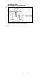
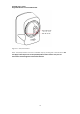
Figure 3-2: PL9850-CMS Right Side Panel
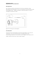
The Rear Panel
The rear panel features two ports:
POWER The POWER port is where you will connect the power adapter.
ETHERNET The ETHERNET port is where you will connect the Ethernet network cable.
Figure 3-3: PL9850-CMS Rear panel
The Product label on the back of the PL9850-CMS displays the following:
Product name
Model number