
User Manual


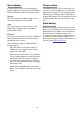

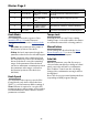


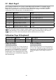
Table Of Contents
- Important Safety Instructions
- Welcome to Hydrasynth!
- Quick Start Guide
- Overview
- Hydrasynth Desktop
- Understanding the Modules
- The Oscillator Group
- The Mixer Module
- The Filters and their Controls
- The Amp Module
- The Envelopes
- The LFOs
- The Effects
- The Voice Module
- Ribbon Controller (keyboard only)
- The Arpeggiator Section
- Mastering the Macros
- The Mod Matrix
- The CV / Gate Section
- Patch Management
- The System Setup Pages
- Control Combinations
- Scales
- Hydrasynth Specifications
- Declaration of Conformity

90
CV – Mods: Page9
These settings enable the use of devices with dierent CV standards. For example, Input /
Output Mod 1 can be set to +/- 5V while Input / Output Mod 2 are set to 0-10V. The Oset
ranges are independent in each direction, which allows the voltages to be ne-tuned to
compensate for the idiosyncrasies of individual devices.
Control knob Function Range
1 IM1 Range (Mod 1 input) +/- 5V, 0-10V, 0-5V, 0-1V
2 IM2 Range (Mod 2 input) +/- 5V, 0-10V, 0-5V, 0-1V
3 OM1 Range (Mod 1 output) +/- 5V, 0-10V, 0-5V, 0-1V
4 OM2 Range (Mod 2 output) +/- 5V, 0-10V, 0-5V, 0-1V
5 IM1 Oset (Mod 1 input) +/- 3.0V
6 IM2 Oset (Mod 2 input) +/- 3.0V
7 OM1 Oset (Mod 1 output) +/- 3.0V
8 OM2 Oset (Mod 2 output) +/- 3.0V
The allowable range for input /output voltages is from -5V to 10V. If an input or output
value attempts to exceed the range, it will be clipped automatically to the lowest or
highest possible value depending on which value has been exceeded.
Calibration: Page 10 (keyboard)
Control button Function Range Description
2 Calibrate Ribbon (access) (see below)
3 Calibrate Wheels (access) Full-range motion of each wheel
Calibrate Ribbon
Keyboard model only: Press Control button 2
to access the calibration page and follow the
instructions on Left display. Press and hold
the ribbon above each C on the keyboard,
including the lowest and highest keys. After
each point has been calibrated the page will
exit automatically.
Calibrate Wheels
Keyboard model only: Press Control button 3
to access the calibration page and follow the
instructions on Left display. Move each wheel
slowly through its entire range, then press
[EXIT].