
User manual

PAGE 5
User Manual BS 181 / May 2013 © ASL Intercom BV
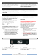
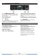
6.0 REAR PANEL CONTROLS & CONNECTORS
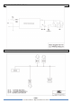
3 INTERCOM LINE connectors
These two XLR-3 connectors are for connecting
the user stations, via standard microphone cable.
Pin assignments:
Pin 1: 0 V / ground shield
Pin 2: +30 V power wire
Pin 3: audio wire
4 FUSE holder
A fuse protects the BS 181 against severe internal
damage in case of malfunction in the power
section. Disconnected the power cord before
replacing the fuse. Place the correct fuse in the
holder: T 1250 mA (for all mains voltages 100 –
240V AC)
An extra internal fuse is located on the printed
circuit board. Replace this fuse with a 4A type only.
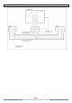
5 MAINS INLET
IEC Mains connector. For correct wiring and
operation refer to section 4.0.
7.0 TECHNICAL SPECIFICATIONS BS 181
Switch Mode Power Supply
mains voltage range: 100 -240 V AC, 50-60 Hz
DC output voltage: +30 V DC (+/-5%)
max. output power: 45 watts
Dimensions & Weight
Width: 176 mm / Height: 42 mm
Depth: 139 mm / Weight: 900 grams
System Specifications
dynamic range: 80 dB (1 kHz, THD < 1%)
frequency response: 200 Hz – 15 kHz (-3 dB)
call signal (send): 2.8 mA
call signal threshold (receive): +2.4 V DC
operating voltage: 24 - 32 V DC
line impedance: 350 Ω (1kHz), 2.2 kΩ (DC)
audio level: nom. -18 dBu, max. 0 dBu
0 dBu defined as 775 mV into open circuit.
ASL reserves the right to alter specifications
without prior notice