
User Manual


Chapter 1: Connections and Setup
Illustrations contained in this document are for representation only.
9
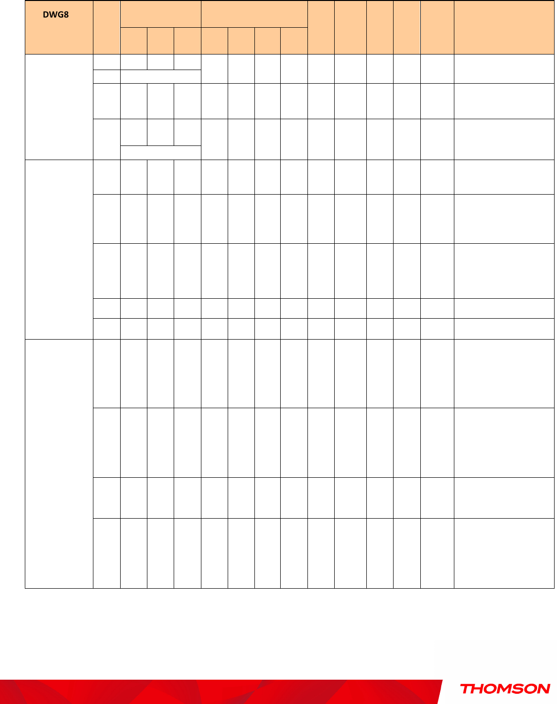
The LEDs on the front panel are described in the table below (from left to right):
DWG875 /
DWG875T
Power
Internet Ethernet
USB
Wireless
Tel 1
Tel 2
Battery
Description
DS US Online
1 2 3 4
Boot-up
Operation
ON ON ON ON
ON ON ON ON On X ON ON X
Power on 0.25 sec
On
0.25 second
ON FLASH
FLASH
FLASH
X X X X X X X X X
From power ON to system
initialization complete
ON
ON ON ON
X X X X X X X X X
Following system initialization
complete to (before)
1 second
DOCSIS Start-
up
Operation
ON FLASH
OFF OFF X X X X X X X X X
During DS scanning and
acquiring SYNC
ON ON FLASH
OFF X X X X X X X X X
From SYNC completed,
receiving UCD to ranging
completed
ON ON ON FLASH
X X X X X X X X X
During DHCP, configuration file
download, registration, and
Baseline Privacy initialization
ON ON ON ON X X X X X X X X X Operational (NACO=ON)
ON FLASH
FLASH
OFF X X X X X X X X X Operational (NACO=OFF)
Channel
Bonding
Operation
FLASH
FLASH
FLASH
FLASH
FLASH
X X X X X X X X
Wait registration with all DS
and all US – Lights Flash
sequentially from the right to
left
X X X X OFF X X X X X
X X X
From 1 to 4 DS, from 1 to 4
LEDs are ON.
From 5 to 8 DS, From 1 to 4
LEDs are flashing
OFF X X X X X X X X X
X X X
From 1 to 4 US, from 1 to 4
LEDs are ON.
FLASH
FLASH
FLASH
FLASH
FLASH
X X X X X
X X X
Wait registration with all DS
and all US – Lights Flash
sequentially from the left to
right