DWG875/DWG875T - Wireless Voice Gateway User manual
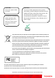
CAUTION CAUTION Disconnect power before To ensure reliable operation and to prevent servicing. overheating, provide adequate ventilation for this modem and keep it away from heat sources. Do not locate near heat registers or other This device is intended for heat-producing equipment. Provide for free air indoor operation only. flow around the Wireless Voice Gateway and its Telephone jacks Line 1 power supply. and Line 2 must not be connected to outside wiring.
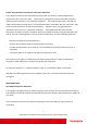
Federal Communication Commission Interference Statement This equipment has been tested and found to comply with the limits for a Class B digital device, pursuant to Part 15 of the FCC Rules. These limits are designed to provide reasonable protection against harmful interference in a residential installation. This equipment generates, uses and can radiate radio frequency energy and, if not installed and used in accordance with the instructions, may cause harmful interference to radio communications.
NORTH AMERICAN CABLE INSTALLER: This reminder is provided to call your attention to Article 820.93 of the National Electrical Code (Section 54 of the Canadian Electrical Code, Part 1) which provides guidelines for proper grounding and, in particular, specifies that the cable ground shall be connected to the grounding system of the building as close to the point of cable entry as practical.
Table of Contents Chapter 1: Connections and Setup ........................................................................................... 5 Introduction ............................................................................................................................ 5 Wireless Voice Gateway Features ....................................................................................... 5 What’s on the CD-ROM ....................................................................................
Table of Contents 2. Connection.................................................................................................................. 26 3. Password..................................................................................................................... 27 4. Diagnostics ................................................................................................................. 30 5. Event Log ......................................................................................
Table of Contents 1. Basic ........................................................................................................................... 50 Gateway – Wireless Web Page Group ...................................................................................... 51 1. 802.11b/g/n Radio ..................................................................................................... 52 2. 802.11b/g/n Primary Network..............................................................................
Table of Contents Glossary ................................................................................................................................ 84 4 Illustrations contained in this document are for representation only.
Chapter 1: Connections and Setup Chapter 1: Connections and Setup Introduction Wireless Voice Gateway Features • High Speed Data Service Solution • DOCSIS 3.0 cable modem • Giga Ethernet router with 4x Standard RJ-45 connectors for 10/100/1000Mbps. Auto-negotiation and MDIS functions • Wi-Fi 802.
Chapter 1: Connections and Setup What’s on the CD-ROM Insert the Wireless Voice Gateway CD-ROM into your CD-ROM drive to view troubleshooting tips, the internal diagnostics, and other valuable information. CD-ROM Contents: • Electronic copy of this user’s guide in additional languages (PDF format) • Adobe Acrobat Reader — application you can load to read PDF format, if you don’t have it loaded already • Links to Thomson web site DOCSIS and PacketCable are trademarks of Cable Television Laboratories, Inc.
Chapter 1: Connections and Setup Computer Requirements For the best possible performance from your Wireless Voice Gateway, your personal computer must meet the following minimum system requirements (note that the minimum requirements may vary by cable companies): IBM PC COMPATIBLE MACINTOSH** CPU Pentium preferred PowerPC or higher System RAM 16MB (32MB preferred) 24MB (32MB preferred) Operating System Windows* NT / 2000 / Me / XP / Mac OS** 7.6.
Chapter 1: Connections and Setup Wireless Voice Gateway Overview Front Panel The following illustration shows the front panel of the Wireless Voice Gateway: 8 Illustrations contained in this document are for representation only.
Chapter 1: Connections and Setup The LEDs on the front panel are described in the table below (from left to right): Internet DWG875 / Ethernet Power DWG875T ON Boot-up USB Wireless Tel 1 Tel 2 Battery Description ON On X ON ON X Power on 0.25 sec X X X X X X DS US Online 1 2 3 4 ON ON ON ON ON ON X X X On 0.
Chapter 1: Connections and Setup Internet DWG875 / Ethernet Power DWG875T DS US Online 1 2 3 4 USB Wireless Tel 1 Tel 2 Battery Description MTA ON ON ON ON X X X X X X FLASH OFF OFF MTA DHCP initialization ON ON ON ON X X X X X X OFF FLASH OFF MTA SNMP/TFTP ON ON ON ON X X FLASH FLASH OFF RSIP for NCS/Register for SIP X X ON X X X X X X X OFF OFF OFF OFF ON ON ON ON No Ethernet Link X X X FLASH FLASH FLASH FLASH CPE Operation TX
Chapter 1: Connections and Setup Rear Panel A TEL1 & TEL2 2x Telephony RJ-11 connectors B ETHERNET 1 2 3 4: 4x Ethernet 10/100/1000 Mbps RJ-45 connectors C USB Host: 1x USB 2.0 Connector D Reset: 1x Reset or reset to factory default this Wireless Voice Gateway 11 Illustrations contained in this document are for representation only.
Chapter 1: Connections and Setup E CABLE: 1x F-Connector for the coax cable F Power Connector: 1x AC Power Connector I WPS & WiFi on/off button: 1x button with two features: to activate/disable the WiFi, to execute a WPS association 12 Illustrations contained in this document are for representation only.
Chapter 1: Connections and Setup Relationship among the Devices This illustration shows a cable company that offers DOCSIS and PacketCable-compliant voice/data services. What the Modem Does The Wireless Voice Gateway provides high-speed Internet access as well as cost-effective, toll-quality telephone voice and fax/modem services over residential, commercial, and education subscribers on public and private networks via an existing CATV infrastructure.
Chapter 1: Connections and Setup What the Modem Needs to Do Its Job The Right Cable Company: Make sure your local cable company provides data services that use cable TV industry-standard DOCSIS compliant and PacketCable compliant technology. The Internet/Telephony Service Provider (ISP/TSP): Your cable company provides you access to an Internet Service Provider (ISP) and Telephony Service Provider (TSP).
Chapter 1: Connections and Setup Contact Your Local Cable Company You will need to contact your cable company to establish an Internet account before you can use your gateway.
Chapter 1: Connections and Setup Connecting the Wireless Voice Gateway to a Single Computer This section of the manual explains how to connect your Wireless Voice Gateway to the USB or Ethernet port on your computer and install the necessary software. Please refer to Figure 1 to help you connect your Digital Cable Modem for the best possible connection. Attaching the Cable TV Wire to the Wireless Voice Gateway 1. Locate the Cable TV wire. You may find it one of three ways: a.
Chapter 1: Connections and Setup Important Connection Information The Wireless Voice Gateway supports Ethernet connection. Below are important points to remember before you connect the Wireless Voice Gateway. For Ethernet connections, go to page 21. For telephone and fax connections, go to page 23. If you do not want to use the CD-ROM, follow instructions 1 through 4 to connect the Wireless Voice Gateway to the Ethernet port on your computer. Instructions must be followed in the order they appear. 1.
Chapter 1: Connections and Setup Ethernet Connection to a Computer Make the connection to the modem in the following sequence: 1. Connect one end of the coaxial cable to the cable connection on the wall, and the other end to the CABLE jack on the Wireless Voice Gateway. 2. Connect the plug from the AC power supply into the POWER AC ADAPTER jack on the Wireless Voice Gateway, and plug the power supply into an AC outlet. Note: Use only the power supply that accompanied this unit.
Chapter 1: Connections and Setup Connecting More Than A Computer to the Wireless Voice Gateway If you need to connect more than one computer to the Wireless Voice Gateway, simply connect the computers to an Ethernet port on the rear panel. Fig.4: Multiple-PC Connection Note: You may need to check with your service provider in order to connect multiple computers. 19 Illustrations contained in this document are for representation only.
Chapter 1: Connections and Setup Telephone or Fax Connection When properly connected, most telephony devices can be used with the Wireless Voice Gateway just as with a conventional telephone service. To make a normal telephone call, pick up the handset; listen for a dial tone, then dial the desired number. For services such as call waiting, use the hook switch (or FLASH button) to change calls.
Chapter 1: Connections and Setup Turning on the Wireless Voice Gateway After installing the Wireless Voice Gateway and turn it on for the first time (and each time the modem is reconnected to the power), it goes through several steps before it can be used. Each of these steps is represented by a different pattern of flashing lights on the front of the modem. Note: All indicators flash once before the initialization sequence.
Chapter 2: WEB Configuration Chapter 2: WEB Configuration To make sure that you can access the Internet successfully, please check the following first. 1. Make sure the connection (through Ethernet or USB) between the Wireless Voice Gateway and your computer is OK. 2. Make sure the TCP/IP protocol is set properly. 3. Subscribe to a Cable Company. 4. Make sure appropriate LEDs are turned on for normal operation as noted in the previous chapter.
Chapter 2: WEB Configuration Outline of Web Manager The main screen will be shown as below. Fig. 7 Outline of Web Manager Main Menu: the hyperlinks on the top of the page, including Gateway, VoIP and several sub-menu items Title: the sidebar on the left side of the page indicates the title of this management interface, e.g.
Chapter 2: WEB Configuration Warning message to change the password At your first connection or while the password is the default one, a warning message is displayed on the top banner of each Web configuration page. We want to encourage you to change the password in order to enforce the security of your modem. Please refer to the chapter “Password” page 27 for more information. 24 Illustrations contained in this document are for representation only.
Chapter 2: WEB Configuration Gateway – Status Web Page Group 1. Software The information section shows the hardware and software information about your gateway. The status section of this page shows how long your gateway has operated since last time being powered up, and some key information the Cable Modem received during the initialization process with your cable company. If Network Access shows “Allowed,” then your cable company has configured your gateway to have Internet connectivity.
Chapter 2: WEB Configuration 2. Connection This page reports current connection status containing startup procedures, downstream and upstream status, CM online information, and so on. The information can be useful to your cable company’s support technician if you’re having problems. Fig. 9 Gateway\Status\Connection 26 Illustrations contained in this document are for representation only.
Chapter 2: WEB Configuration 3. Password Forcing end user to change the password Upon access to the web pages on the CPE side of the router, if the user has not changed the default web password, a warning message must be displayed in the top banner of the web interface such as being visible while accessing any tabs. This warning message informs the user that the default password must be changed: In the second sentence, “here” is a hyperlink to the password setting page.
Chapter 2: WEB Configuration The password can be a maximum of 8 characters and is case sensitive. In addition, this page can be used to restore the gateway to its original factory settings. Use this with caution, as all the settings you have made will be lost. To perform this reset, set Restore Factory Defaults to Yes and click Apply. This has the same effect as a factory reset using the rear panel reset switch, where you hold on the switch for 15 seconds, then release it.
Chapter 2: WEB Configuration If the password is not accepted, an error message is displayed: Click on try again. 29 Illustrations contained in this document are for representation only.
Chapter 2: WEB Configuration 4. Diagnostics This page offers basic diagnostic tools for you to utilize when connectivity problems occur. When you ping an Internet device, you send a packet to its TCP/IP stack, and it sends one back to yours. To use the ping Test, enter the information needed and press Start Test; the Result will be displayed in the lower part of the window. Press Abort Test to stop, and Clear Results to clear the result contents.
Chapter 2: WEB Configuration 5. Event Log This page displays the contents of the SNMP event log. Press “Clear Log” button to clear the logs. Fig. 12 Gateway\Status\Event Log 31 Illustrations contained in this document are for representation only.
Chapter 2: WEB Configuration 6. Backup/Restore Backup/Restore Settings : This page allows you to save your current settings locally on your PC, or to restore settings saved previously. The file name is “GatewaySettings.bin”. Fig 13 Gateway\Status\Backup/Restore 32 Illustrations contained in this document are for representation only.
Chapter 2: WEB Configuration Gateway – Network Web Page Group 1. LAN You can activate the DHCP server function for the LAN on this page. With this activated function, • your cable company’s DHCP server provides one IP address for your gateway, • and your gateway’s DHCP server provides IP addresses, starting at the address you set in IP Address on the LAN page, to your PCs. A DHCP server leases an IP address with an expiration time.
Chapter 2: WEB Configuration 2. WAN You can configure the optional internal DHCP server for the WAN on this page. This can be required by some ISP providers. Select different WAN Connection Type will lead to different contents. Take the WAN connection type-DHCP for example, you can release and renew the WAN lease by pressing the buttons. You can enter a spoofed MAC address that causes your gateway networking stack to use that MAC address when communicating instead of the usual WAN MAC address, e.g.
Chapter 2: WEB Configuration 3. Computers This page displays the status of the DHCP clients and current system time. You can cancel an IP address lease by selecting it in the DHCP Client Lease Info list and then clicking the Force Available button. If you do so, you may have to perform a DHCP Renew on that PC, so that it can obtain a new lease. Fig. 16 Gateway\Network\Computers 35 Illustrations contained in this document are for representation only.
Chapter 2: WEB Configuration 4. DDNS - Dynamic DNS service This page allows to setup for Dynamic DNS server. Fig 17 Gateway\Network\DDNS 36 Illustrations contained in this document are for representation only.
Chapter 2: WEB Configuration 5. Time server This page allows configuration and display of the system time obtained from network servers via Simple Network Time Protocol. The system has to be reset for any changes to take effect. Fig 18 Gateway\Network\Time 37 Illustrations contained in this document are for representation only.
Chapter 2: WEB Configuration Gateway – Advanced Web Page Group 1. Options This page allows you to enable/disable some features of the Wireless Voice Gateway. Fig. 19 Gateway\Advanced\Options WAN Blocking prevents others on the WAN side from being able to ping your gateway. With WAN Blocking enabled, your gateway will not respond to pings it receives, effectively “hiding” your gateway. Ipsec PassThrough enables IpSec type packets to pass WAN LAN.
Chapter 2: WEB Configuration discover the services from other registered UPnP devices on the network. NatSipAlg Enable the gateway implements SIP ALG (Application-level gateway). It is enabled by default and help in solving NAT related problems in client LAN side. 39 Illustrations contained in this document are for representation only.
Chapter 2: WEB Configuration 2. IP Filtering This page enables you to enter the IP address ranges of PCs on your LAN that you don’t want to have outbound access to the WAN. These PCs can still communicate with each other on your LAN, but packets designated to WAN addresses are blocked by the gateway. Fig. 20 Gateway\Advanced\IP Filtering 40 Illustrations contained in this document are for representation only.
Chapter 2: WEB Configuration 3. MAC Filtering This page enables you to enter the MAC address of specific PCs on your LAN that you do not wish to have outbound access to the WAN. As with IP filtering, these PCs can still communicate with each other through the gateway, but packets they send to WAN addresses are blocked. Fig. 21 Gateway\Advanced\MAC Filtering 41 Illustrations contained in this document are for representation only.
Chapter 2: WEB Configuration 4. Port Filtering This page allows you to enter ranges of destination ports (applications) that you don’t want your LAN PCs to send packets to. Any packets your LAN PCs send to these destination ports will be blocked. For example, you could block access to worldwide web browsing (http = port 80) but still allow email service (SMTP port 25 and POP-3 port 110). To enable port filtering, set Start Port and End Port for each range, and click Apply.
Chapter 2: WEB Configuration 5. Forwarding For LAN WAN communications, the gateway normally only allows you to originate an IP connection with a PC on the WAN; it will ignore attempts of the WAN PC to originate a connection onto your PC. This protects you from malicious attacks from outsiders. However, sometimes you may wish for anyone outside to be able to originate a connection to a particular PC on your LAN if the destination port (application) matches one you specify.
Chapter 2: WEB Configuration 6. Port Triggers Some Internet activities, such as interactive gaming, require that a PC on the WAN side of your gateway be able to originate connections during the game with your game playing PC on the LAN side. You could use the Advanced-Forwarding web page to construct a forwarding rule during the game, and then remove it afterwards (to restore full protection to your LAN PC) to facilitate this.
Chapter 2: WEB Configuration 7. DMZ Host Use this page to designate one PC on your LAN that should be left accessible to all PCs from the WAN side, for all ports. For example, if you put an HTTP server on this machine, anyone will be able to access that HTTP server by using your gateway IP address as the destination. A setting of “0” indicates NO DMZ PC. “Host” is another Internet term for a PC connected to the Internet. Fig. 25 Gateway\Advanced\DMZ Host 45 Illustrations contained in this document are for