
User's Manual


HARDWARE INSTALLATION
4
2. HARDWARE INSTALLATION
This section includes physical description and installation procedure of the
cable modem.
2.1 Physical Description
2.1.1 Front Panel Indicators
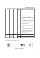
Figure 2-1: Front Panel LEDs
Four LEDs on the front panel (as figure 2-1) provide status indication of cable
modem operation. They are listed in the table below in order as viewed from
upper to under.
LEDs Function Color Active Description
POWER Power Green On Power is being applied to CM.
On Ethernet/USB carrier is present.PC Link/PC
Data
Green
Blinking To indicate Ethernet or USB data.
CABLE RF Data Green Blinking To indicate transmit RF US traffic.
STATUS Link Green On Modem registration completed.