Installation and Maintenance Instructions for GC55 Differential Pressure Transducer Version 1.0 5/11 © 2012 Ashcroft Inc. 250 East Main Street, Stratford, CT 06614 USA Tel: 203-378-8281, Fax: 203-385-0402 www.ashcroft.com All sales subject to standard terms and conditions of sale. I&M011-10158. Rev.
WARNING! READ BEFORE INSTALLATION 1. GENERAL: A failure resulting in injury or damage may be caused by excessive overpressure, excessive vibration or pressure pulsation, excessive instrument temperature, corrosion of the pressure containing parts, or other misuse. Consult Ashcroft Inc., Stratford, Connecticut, USA before installing if there are any questions or concerns. 2.
ConTenTs 1. specifications .................................................. 6 2. Dimension Drawings ...................................... 7-8 3. Installation ........................................................ 8 4. Wiring ................................................................ 9 5. noise Prevention.............................................. 9 6. storage .............................................................. 9 7. Maintenance ............................................
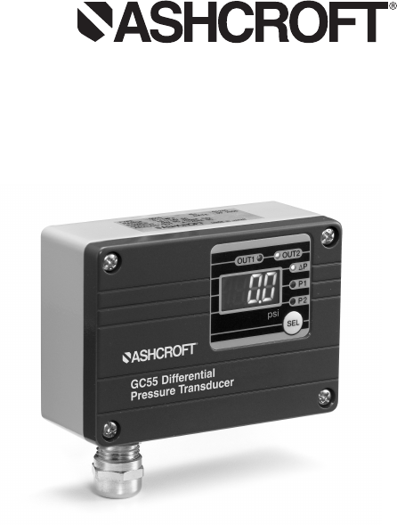
1. specifications* Pressure Range*: 75, 100, 150, 250, 300 psid (as noted on the unit) Proof Pressure*: 2X F.S. Differential Pressure Range (DP): DP=P1(H)-P2(L); as marked on unit Display Range: Diff. pressure range of –5 to 105%F.S. or display of –1999 to 1999 Power supply: • 4-20ma Output Version: 15-27 Vdc, 80mA • 1-5 Vdc Output Version: 11-27 Vdc, 60mA Display: 31⁄2 digit LED (digit height: 10mm) Display accuracy DP : ±(1.0%F.S.+1 digit) P1, P2 : ±(0.5%F.S.+1 digit) Update Time: 0.
operating humidity range: 10 to 85%(with no condensation) storage Temperature: –20 to 60°C (–4 to 140°F) (non freezing) Case construction: IP65/NEMA 4 Pressure Connections: 1⁄8 NPT Female (2) places enclosure Material: Aluminum Weight: 18 ounces Notes: *Maximum operating static (line) pressure is the full scale range of the unit ordered/specified.
3. Installation Install in a location where vibration and shock can be minimized and without direct sunlight on the display in compliance with IP64 environmental rating. • Pressure Port Connections: 1⁄8 NPT female, 11⁄2 turns past hand tight. • Mounting: Remove the GC55 cover, 4 screws, and attach via through holes, (2) places, 0.20˝ diameter.
4. Wiring Terminal strip Designations The terminals are as shown below. Connect power only after checking wiring. After power is turned on, wait at least 15 minutes before performing a zero adjustment or measurement. Power supply (+) Power supply (−) OUT 1 (Switch) output state OUT 2 (Switch) COM. (Switch) Analog output Applicable wire 16-22 AWG Cable Gland or 1/2 FNPT Conduit Connection 5.
Illustration (1) Illustration (2) 10
8. Menu navigation (cont.) External Panel and Functions (SEL key can be operated externally) Illustration (3) 8. Menu navigation (cont.
8. Menu navigation (cont.) Pressing the MODE key for 3 seconds displays “---”. To return to measurement mode from each setting mode, the “---” display will flash when 3 seconds have passed. *Note: Zero Adjustment, select P1 and P2 respectively and then use Zero Adjustment, will not function in DP mode. 9. Function setting Mode setup steps Pressing the MODE key for 3 seconds displays “---”. To return to measurement mode from each setting mode, the “---” display will flash when 3 seconds have passed.
Entering the setting value in function setting mode resets all of the setting values including the switch. Please note that when the reset setting values are out of the display range, they will be adjusted to an upper or lower limit value that can be processed internally. switch operation Select “Switch Operation Selection” with the MODE key. The message [np is displayed for 1 sec. and then the current setting is displayed. Select either hysteresis or switch operation display with the ▲▼ keys.
Entering the setting value in function setting mode resets all of the setting f-0 - - - - f-1 - - - - f-2 - - - - - Time constant 25ms f-3 - - - - f-4 - - - - f-5 - - - - - Time constant 5 sec No filter Time constant 250ms Time constant 2.5 sec Time constant 10sec Analog selection Select “Analog Selection” with the MODE key. The message is ana displayed for 1 sec. and then the pressure of analog output is displayed. Select DP, P1 or P2 with the ▲▼ keys.
independently to a max on/off delay of 2 seconds. In the following explanation, if the switch’s output conditions are met their output state will become On, and “Switch LED (OUT1, OUT2)” will light up. PLEASE NOTE that if the switch’s setting value is set outside the display range, the switch’s setting value can be rewritten automatically by the function setting mode operation.
11. switch operation – Hysteresis/Deadband setting the upper limit. This is the mode in which the switch operates with the setting value (A) as the upper limit. The upper limit setting is determined when you select a positive number (including 0) for setting value (b). setting the lower limit. This is the mode in which the switch operates with the setting value (A) as the lower limit.
operation of Window Comparator 12. Loop Check Mode setup steps In measurement mode press the MODE + ▲ key (release within 3 sec.) to change to Loop Check Mode. Regardless of applied pressure, display and analog output can be tested manually using the ▲▼ keys, useful for simulation testing of the analog output and switch output wiring. After the switch setting press lop for 1 sec. to change into Loop Check Mode. The initial value will be the value displayed immediately before entering Loop check mode.
Less than 1 sec. 13. other Functions Basic Key operations In all setting modes, values are set with the ▲▼ keys. Use the ▲ key to increase and the ▼ key to decrease the value. A repeat state occurs in three phases of speed when the ▲▼ keys are pressed for more than 0.5 seconds to increase or decrease numerical value. ▲▼ keys are also used for setting switch, unit and filter in the function setting mode. Adjusting the zero point of P1, P2 In measurement mode, select display to adjust zero using SEL key.
When zero adjustment is successful, adj displays. When in –1999 to 1999 of display range, adjustment can be done. On DP display scaling of function mode et[ , zero adjustment value is reset and returns to initial value when each setting changes. e-0 displays for 1 second when DP zero adjustment cannot be done. Maximum / Minimum Pressure Capture The GC55 unit keeps the maximum and minimum pressure level applied to the pressure port as peak and bottom values respectively, in the internal memory.
error Display An error message and a pressure are alternately displayed when one of the following errors occurs while in measurement mode. error Display FFF * -FFF Definition Definition Pressure above 105% F.S. of sensor range is applied, or when indicated value exceeded 1999. (If pressure display is not selected, LED blinks.) Return pressure to within rated range. Pressure less than –5% F.S. of sensor range is applied, or when indicated value exceeded –1999.
14. MAInTenAnCe AnD WARRAnTY 䡲 䡲 䡲 Periodic Inspection Depending upon the type of use periodic inspection is recommeded at least once a year. Please refer to the following items for periodic inspection. (1) Appearance (2) Display/output check via appropriate pressure standard(1) (3) Display/output check via Loop Check(2) CAUTIon • Avoid electrostatic charging. When cleaning this product, please use a soft, damp, cloth. • Do not use thinner, etc. which may cause deterioration and failure.
© 2012 Ashcroft Inc. 250 East Main Street, Stratford, CT 06614 USA Tel: 203-378-8281, Fax: 203-385-0402 www.ashcroft.com All sales subject to standard terms and conditions of sale. I&M011-10158. Rev.