Quick Start Function Summary Instructions for ASHCROFT® GC52 Differential Pressure Transmitter Version 6.03 Rev. B (See Complete I&M Manual for Further Detail) LOOK FOR THIS AGENCY MARK ON OUR PRODUCTS © 2010 Ashcroft Inc., 250 East Main St., Stratford, CT 06614-5145, USA, Tel: 203-378-8281, Fax: 203-385-0499, www.ashcroft.com All sales subject to standard terms and conditions of sale. I&M011-10164-GC52 Ver. 6.03 Rev.
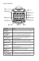
DISPLAY OVERVIEW Test Terminals CH+ g Linear scaling mode CH– GC52 b Differential pressure unit monitor h No function In H2O c Scaling - Arbitrary unit monitor 8.8.8.8.8.8.
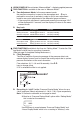
1. UPON POWER-UP the unit enters “Measure Mode” – displaying applied pressure. 2. TWO FUNCTION is available to the user in “Measure Mode”. A.
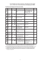
3. To adjust Output Zero Point (4mA) and Output Span Point (20mA) the unit must be in the functional area as noted below while adjustment is via $ # keys. The value shown is a percentage of the pressure range (span) as noted on the product label (ex. If product was supplied as a 0-40 IWC range and the user desired the Output Zero Point (4mA) to be “moved” from 0 IWC to 20 IWC then Output Zero Point would be 50.0 which is 50%. Values shown below are from I&M manual.
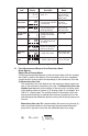
LCD Display Display mode n00l0n Selection of linear display mode: Lin non: Differential pressure display mode; Lin: Linear display mode Min. differential pressure p0 -20 Min. differential pressure corresponding to OFFSET :20.0(inH2O) Differential pressure range: 0 to 75% Span Max. differential pressure p0-120 Max.
In addition, the coefficient k is determined by substituting the maximum momentary flow rate Dm, which is measured from the formula (a), and the then generated differential pressure Pm into the formula (b). (b) k= 公 Dm00 Pm 100 • The differential pressure generated during the maximum momentary flow rate can be set in the range of 25 to 100%F.S. of the differential pressure range. • The setting range for values of the maximum momentary flow rate is 0 to 1999.
• The indicated value which is blinking is integrated during the "blink" display at the time of momentary flow rate display span OVER. Flow Measurement/Square Root Extraction Mode No. Setting Item Display mode 21 22 23 Maximum differential selection1 Flow rate decimal pt. position Max. momentary flow Low cut ~n roT D Displays of value after deci- 0,1,2,3 digit mal point, # of digits 0 A 0.0 Output span point2 A100.0 U SE[ U 1 s bT T 5 c 0.0 25 to 100% F.S.
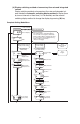
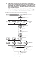
(4) Display switching method of momentary flow rate and integrated volume Display switching methods of momentary flow rate and integrated volume include the automatic switching display method to display them by turns at intervals of fixed time (1 to 10 seconds) and the manual switching display method to change the display by pressing (M) key. Complete Setting Mode Menu u M key for more than 3 seconds Measurement Mode Setting Mode u 6.
E. Loop Check: Use to send a 4-20mA signal meant to simulate applied pressure, can be accessed either through Pressure Display Mode or Linear Display Mode. See “Complete Setting Mode Menu”; Loop Check is noted on the screen with a prefix “(”. The display is indicating in actual units and starts at the zero (4mA) point. If $ button is pressed, the linear display will auto increment by linkage between the linear display and the analog output. By continuing to press # button, auto decrement will occur.
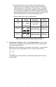
4. WIRING Power supply requirements, 12-36Vdc, note installation recommendations as follows: Terminal Strip: SMKDSP1.5/2-5.08 Phoenix contact A. Cable Requirements • Two core shielded cable • Cable outer diameter: 0.35˝ to 0.47˝ (9-12mm) Required for proper installation with cable gland option • Wire Gauge: 14-22 AWG (multi-strand or solid) Power source + − Receiver + − Transmission cable Terminal box Shield Display (board) B.
• Remove cover and carefully remove the display to access the terminal strip, take care not to mishandle the display and associated electronics. • Turn display over to expose terminal strip, make positive and negative connections; insert wire equal to the recommended strip length (0.25˝). • After completing connections, align the retaining clips of the display with the housing’s notches and carefully place into the housing.
Load Limitations 4-20mA Output Only Loop Resistance (V) 1020 1000 750 545 500 OPERATING REGION 250 0 0 10 12 20 24 30 32 LOOP SUPPLY VOLTAGE Vmin = 12V+[.
© 2010 Ashcroft Inc., 250 East Main St., Stratford, CT 06614-5145, USA, Tel: 203-378-8281, Fax: 203-385-0499, www.ashcroft.com All sales subject to standard terms and conditions of sale. I&M011-10164-GC52 Ver. 6.03 Rev.