Installation and Maintenance Instructions for GC35 Heavy Duty Digital Pressure Sensor Version 1.0 5/11 © 2011 Ashcroft Inc. 250 East Main Street, Stratford, CT 06614 USA Tel: 203-378-8281, Fax: 203-385-0402 www.ashcroft.com All sales subject to standard terms and conditions of sale. I&M011-10172 .
CONTENTS 4 CAUTION ........................................................................................................................ 5 1. SPeCIfICATIONS .......................................................................................................... 2. DIMeNSION DrAwINGS................................................................................................ 6 3. INSTAllATION .............................................................................................................
WARNING! READ BEFORE INSTALLATION 1. GENERAL: A failure resulting in injury or damage may be caused by excessive overpressure, excessive vibration or pressure pulsation, excessive instrument temperature, corrosion of the pressure containing parts, or other misuse. Consult Ashcroft Inc., Stratford, Connecticut, USA before installing if there are any questions or concerns. 2.
1. SPECIFICATIONS: PERFORMANCE SPECIFICATIONS Optional Analog Output (4-20mA): Accuracy ±1.0% FS (Accuracy includes the effects of Linearity, Hysteresis and Repeatability) Response Time: 30msec–10 sec (by user) Output Resolution: ±0.05 FS Analog Scaling: User may configure analog output scaling to any range within –100 to 150% Full Scale of sensor range. Pressure Switch Output: Type: NPN or PNP Open Collector up to 80mA Setting Accuracy: ±1.
MECHANICAL SPECIFICATIONS Pressure Connection: 1⁄4 NPT (Male) Connection Location: Lower, Back Enclosure: Nickel Plated Aluminum Rating: IP67 (Ranges 300 psi and above); IP65 (Ranges 150psi and below) Electrical Connection: M12 Connector (4 pin) Weight: Approx. 150 grams Media: Fluids and gases compatible with 316SS (sensing housing) and 17-4 pH SS (sensor diaphragm) 2. PRODUCT DIMENSIONS: lower Connect Back Connect 58 8 Ø 2.2 53 2.05 39 1.51 25 .96 34 1.34 24 .94 72 2.83 34 1.34 89 . 50 3 Ø 57 2.
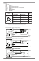
4. WIRING: Cable Color Red Power (+) Open Collector Output OUT 1 Black White Open Collector Output OUT 2 / analog output Green Power (−) Shielded Ground Silver Clear Vent Tube TERMINAL NUMBER WIRING PIN OUT 2 3 Pin 611C175 Cable Wiring Color 2 Switch (No 4-20mA) 1 Switch Analog Output 1 Power (+) Power (+) 2 OUT2 Analog (+) Output WHITE 3 Power (–) Power (–) GREEN 4 OUT1 OUT1 BLACK RED 1 4 NOTE: Mount M12 connector pins face on with electrical mating cable.
PNP Type Switch Function (Wiring to Relay) Red GC35 1 Black 4 Relay protective transistor diode (make sure to install) (OUT1) 30Vdc/80mA max. White Relay (OUT2) 2 Relay output Green 3 Power (+) Power (−) NOTE: Confirm the relay’s rated current and voltage are within the transistors rating. PNP Type Switch Function (Wiring to Photo Coupler) Red GC35 Power (+) 1 Black 4 (OUT1) Photo coupler 30Vdc/80mA max.
5. NOISE PREVENTION Power Supply The pressure display can fluctuate and provide incorrect output if noise is present in the power supply/wires. Care should be taken to keep the GC35 power supply wires from high voltage lines and use a power line with a high noise rejection ratio. 6. STORAGE Store in a location in compliance with the environmental rating of the unit and within –20 to +70°C (–4 to 158°F). Avoid direct exposure of the display to Sunlight. 7.
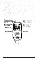
Pressing the MODE key for 3 seconds displays “_ _ _”. To return to measurement mode, the “_ _ _” display will flash when 3 seconds have passed.
Measurement Mode MODE Press 3 sec. or longer MODE Press 3 sec.
Indication Scaling In (Display setting), when (indication scaling) is selected, arbitrary scaling value, based on the applied pressure, can be displayed on the unit. This feature can scale the display value based on the minimum and maximum pressures within the rated pressure range, and will not affect the analog or switch output. • Decimal Point Placement 0 No decimal point 䡺 0 One digit after decimal point 0. 䡺 0. 0 0 Two digits after decimal point 䡺 0.
10. COMPArATOr SwITCH SeTTING MODe / lOOP CHeCK MODe Setup Steps Pressing the MODE key for less than 3 seconds will display message within the Comparator Setting/Loop Check Mode. Scroll through appropriate displays and select feature to change/confirm. LED ring will flash until this menu is exited to the Measurement Mode by holding the MODE key for more than 3 seconds. Measurement Mode MODE Press less than 3 sec. MODE Press 3 sec.
In “Comparator setting mode”, user can change settings on the comparator outputs provided by the unit. (Two comparator outputs or one for analog output unit are provided). The available selections of this mode varies based on the selections made in Function setting mode and comparator output type selection. For the unit provided with two comparator outputs, settings of each output can be done independently with the exception of the operation mode.
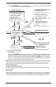
11. COMPArATOr SwITCH OPerATION When the comparator output conditions shown below are met, each output becomes ON status and "Comparator output LED (OUT1, OUT2)" is red lit. • Operation of hysteresis mode Setting the lower limit Pressure Setting the upper limit Pressure Setting point (A) (dead-band) (A) – (b) Setting point (A) (A) – (b) Setting point (b) dead-band Time Time ON OFF ON OFF The lower limit setting is determined when you select a negative number for setting value (b).
12. OTHer fUNCTIONS Basic Key Operations For setting up in each setting mode, the contents of selection UP/DOWN keys are chosen, respectively. In all setting modes, values are set with the UP/DOWN keys. Use UP key to increase and DOWN key to decrease values. A repeat state occurs in three phases of speed when the UP or DOWN keys are pressed for more than 0.5seconds to increase or decrease numerical value.
Error Display FFF 䡺 FFF 䡺 E-0 䡺 Contents Actions Out of pressure display range (Upper limit) A pressure above 110% FS of pressure range is applied, or when indicated value Adjust the applied pressure exceeds 1999. within the rated pressure. Out of pressure display range (Lower limit) A pressure less than –10% FS of pressure range is applied, or when indicated value falls below –1999.
15. Maintenance and Warranty Periodic Inspection Depending upon the type of use periodic inspection is recommended at least once a year. Please refer to the following items for periodic inspection. 1. Appearance 2. Display/output check via appropriate pressure standard(1) 3. Display/output check via Loop Check(2) CAUTION • Avoid electrostatic charging. When cleaning this product, please use a soft, damp cloth. • Do not use thinner, etc. which may cause deterioration and failure.
© 2011 Ashcroft Inc. 250 East Main Street, Stratford, CT 06614 USA Tel: 203-378-8281, Fax: 203-385-0402 www.ashcroft.com All sales subject to standard terms and conditions of sale. I&M011-10172. Rev.