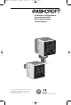
I&M011-10170 GC31:layout 4/8/10 3:26 PM Page 1 Installation and Maintenance Instructions for GC31 Ultra-Compact Digital Pressure Sensor Ashcroft Inc. 250 East Main Street, Stratford, CT 06614 USA Tel: 203-378-8281, Fax: 203-385-0402 www.ashcroft.com All sales subject to standard terms and conditions of sale. © 2009 I&M011-10170 -01/10 LOOK FOR THIS AGENCY MARK ON OUR PRODUCTS 1 Version 5.
I&M011-10170 GC31:layout 4/8/10 3:26 PM 2 Page 2
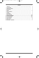
I&M011-10170 GC31:layout 4/8/10 3:26 PM Page 3 CONTENTS CAUTION ........................................................................................................................ 1. SPECIFICATIONS ............................………………………………………………………. 2. DIMENSION DRAWINGS ............................……………………………………………….. 3. INSTALLATION............................………………………………………………………….. 4. WIRING ..............................………………………………………………………………. 5. NOISE PREVENTION ............................
I&M011-10170 GC31:layout 4/8/10 3:26 PM 4 Page 4
I&M011-10170 GC31:layout 4/8/10 3:26 PM Page 5 WARNING! READ BEFORE INSTALLATION 1. GENERAL: A failure resulting in injury or damage may be caused by excessive overpressure, excessive vibration or pressure pulsation, excessive instrument temperature, corrosion of the pressure containing parts, or other misuse. Consult Ashcroft Inc., Stratford, Connecticut, USA before installing if there are any questions or concerns. 2.
I&M011-10170 GC31:layout 4/8/10 3:26 PM Page 6 1. SPECIFICATIONS: PERFORMANCE SPECIFICATIONS Analog Output (1–5Vdc): Accuracy: ±1.0% FS (Accuracy includes the effects of Linearity, Hysteresis and Repeatability) Response Time: 50msec Output Resolution: 25mV Analog Scaling: User may configure analog output scaling to any range within Full Scale of sensor range Pressure Switch Output: Type: NPN or PNP Open Collector up to 30Vdc/80mA Setting Accuracy: ±1.0% FS Number of Contacts: 2 Response Time: 5msec-2.
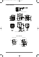
I&M011-10170 GC31:layout 4/8/10 3:26 PM Page 7 2. PRODUCT DIMENSIONS Product label 40 1.57 30 1.18 30 1.18 20 .79 PRESSURE SENSOR OUT1 OUT2 20 .79 30 1.18 PSI ADJ. MODE Back Connect Type with 1⁄4NPT Male (G1⁄4B optional) 32 1.26 PRESSURE SENSOR OUT1 OUT2 ADJ. 40 1.57 PSI MODE 9 .35 Lower Connect Type with 1⁄4NPT Male (G1⁄4B optional) PROCESS CONNECTIONS 1⁄4NPT Male Standard G1⁄4B (PF) Optional [17] HEX .67 [7] .28 [7] .28 [17] HEX .67 [16] .63 [5] .12 [16] .
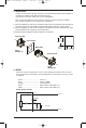
I&M011-10170 GC31:layout 4/8/10 3:26 PM Page 8 3. INSTALLATION Install in a location where vibration and shock can be minimized and without direct sunlight on the display in compliance with IP40 environmental rating. (Pressure port connection: 1⁄4NPT male 11⁄2 turns hand tighten.) Note: Panel mount adapter for back connection only. Do not attach panel mount adapters prior to panel installation or out of sequence as stated below. 1.
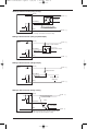
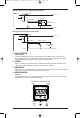
I&M011-10170 GC31:layout 4/8/10 3:26 PM Page 9 NPN Type Switch Function (wiring to relay) GC31 (Brown) Power (+) Relay Output (Black-White) Relay 80mA max. Protective transistor diode (ensure to install) (Blue) Power (–) Note: Ensure that the relay’s operation coil rated current and voltage are within the transistor’s rating. NPN Type Switch Function (wiring to photocoupler) GC31 (Brown) Power (+) Electric current resistance (Black-White) Open collector output 80mA max.
I&M011-10170 GC31:layout 4/8/10 3:26 PM Page 10 PNP Type Switch Function (wiring to photocoupler) GC31 (Brown) Power (+) Photo coupler (Black-White) Open collector output 80mA max. Electric current resistance (Blue) Power (–) PNP Type Switch Function (voltage output) GC31 (Brown) Power (+) Pulldown resistance (Black-White) 80mA max. Voltage HL output (High/Low) (Blue) Power (–) 5.
I&M011-10170 GC31:layout 4/8/10 3:26 PM Page 11 Pressing the MODE key for 3 seconds displays “---”. To return to measurement mode from each setting mode, the “---” display will flash when 3 seconds have passed.
I&M011-10170 GC31:layout 4/8/10 3:26 PM Page 12 Measurement Mode MODE MODE Press > 3 sec. Press > 3 sec. Select with Function Setting Mode (nP (Comparator operation selection) Message displayed kY5 Hys or !;n Current setting Hysteresis XW After 1 second un; (Display selection) Message displayed MODE (Only in keys kY5 Win Window comparator Select with MODE (In SI unit selection) XW After 1 second ETC Current unit setpoint MODE et( d-P .
I&M011-10170 GC31:layout 4/8/10 3:26 PM Page 13 9C. SELECTING STANDARD OR CUSTOM SCALING MODE When the et( is selected in “Display Selection”, the display value of pressure for applied pressure displays as an arbitrary scaling display. This is a function to scale the MIN/MAX display value and has NO effect on applied pressure and analog output. 9D.
I&M011-10170 GC31:layout 4/8/10 3:26 PM Page 14 NOTE: if the switch’s setting value is set outside the display range, the switch’s setting value can be rewritten automatically by the function setting mode operation. Measurement Mode MODE Press < 3 sec. MODE Press > 3 sec. Comparator Setting Mode Loop Check Mode After 1 second (Output1. Comparator setting point A) MODE a-1 50.0 XW Set any desired value within the –1999 to 1999 range with Up/Down keys Message displayed After 1 second (Output1.
I&M011-10170 GC31:layout 4/8/10 3:26 PM Page 15 11. SWITCH OPERATION – HYSTERESIS/DEADBAND Setting the upper limit This is the mode in which the switch operates with the setting value (A) as the upper limit. The upper limit setting is determined when you select a positive number (including 0) for setting value (b). Setting the lower limit . . . . . . . . This is the mode in which the switch operates with the setting value (A) as the lower limit.
I&M011-10170 GC31:layout 4/8/10 3:26 PM Page 16 Loop check function At the end of the Switch Operation Menu is the Loop Check function. Using the MODE key to select the Loop Check function. After lop is displayed for 1 second, the value of the latest measurement mode is displayed as default. Use keys to set displayed value anywhere between –1999 and 1999 to confirm switch operations and/or analog output operation. 12.
I&M011-10170 GC31:layout 4/8/10 3:26 PM Page 17 Maximum/Minimum Pressure Capture The GC31 unit keeps the maximum and minimum pressure level applied to the pressure port as peak and bottom values respectively, in the internal memory. The peak and bottom values are displayed while holding the or keys respectively. Message pe+ is displayed for one second and selected Max/Min value is displayed by this operation.
I&M011-10170 GC31:layout 4/8/10 3:26 PM Page 18 14. MAINTENANCE AND WARRANTY Periodic Inspection Depending upon the type of use periodic inspection is recommended at least once a year. Please refer to the following items for periodic inspection. 1. Appearance 2. Display/output check via appropriate pressure standard(1) 3. Display/output check via Loop Check(2) CAUTION • Avoid electrostatic charging. When cleaning this product, please use a soft, damp cloth. • Do not use thinner, etc.
I&M011-10170 GC31:layout 4/8/10 3:26 PM 19 Page 19
I&M011-10170 GC31:layout 4/8/10 3:26 PM © 2009 Ashcroft Inc. 250 East Main Street, Stratford, CT 06614 USA Tel: 203-378-8281, Fax: 203-385-0402 www.ashcroft.com All sales subject to standard terms and conditions of sale.