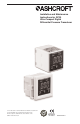
Installation and Maintenance Instructions for GC30 Ultra-Compact Digital Differential Pressure Transducer © 2011 Ashcroft Inc. 250 East Main Street, Stratford, CT 06614 USA Tel: 203-378-8281, Fax: 203-385-0402 www.ashcroft.com All sales subject to standard terms and conditions of sale. I&M011-10169 Rev. A 5/11 LOOK FOR THIS AGENCY MARK ON OUR PRODUCTS 1 Version 5.
CONTENTS 4 CAUTION ........................................................................................................................ 5 1. SPeCIfICATIONS .......................................................................................................... 2. DIMeNSION DrAwINGS................................................................................................ 6 3. INSTAllATION .............................................................................................................
WARNING! READ BEFORE INSTALLATION 1. GENERAL: A failure resulting in injury or damage may be caused by excessive overpressure, excessive vibration or pressure pulsation, excessive instrument temperature, corrosion of the pressure containing parts, or other misuse. Consult Ashcroft Inc., Stratford, Connecticut, USA before installing if there are any questions or concerns. 2.
1. SPECIFICATIONS: PerfOrMANCe SPeCIfICATIONS Analog Output (1–5Vdc): Accuracy ± 1.5% FS (Accuracy includes the effects of Linearity, Hysteresis and Repeatability) Response Time: 50msec Output Resolution: 25mV Analog Scaling: User may configure analog output scaling to any range within Full Scale of sensor range. Pressure Switch Output: Type: NPN or PNP Open Collector up to 30Vdc/80mA Setting Accuracy: ± 1.5% FS Number of Contacts: 2 Response Time: 5msec–2.
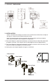
2. PrODUCT DIMeNSIONS: 3. INSTAllATION Install in a location where vibration and shock can be minimized and without direct sunlight on the display in compliance with IP40 environmental rating. Note: Panel mount adapter for back connection only. Do not attach panel mount adapters prior to panel installation or out of sequence as stated below. 1.) Take Panel Adapter #1 (tube notch faced down) and mount to the main body with panel placed in between as pictured.
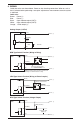
4. wIrING Cable wire colors are shown below. Power on after checking connections. When on, wait at least 5 minutes before performing a zero point adjustment or measurement to ensure system is stabilized. Cable color Brown: Power (+) Power (–) Blue: Black: Open collector output (OUT1) White: Open collector output (OUT2) Orange: 1-5Vdc output (+) Analog Output (1-5VDC) GC30 (Brown) Power (+) (Black-White) (Orange) 1-5Vdc Load 10k V min.
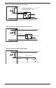
PNP Type Switch function (wiring to relay) GC30 (Brown) Power (+) Protective transistor diode (ensure to install) (Black-White) Relay 80mA max. Relay Output (Blue) Power (–) Note: Ensure that the relay’s operation coil rated current and voltage are within the transistor’s rating. PNP Type Switch function (wiring to Photo Coupler) GC30 (Brown) Power (+) Photo coupler (Black-White) Open collector output 80mA max.
5. NOISe PreVeNTION Power Supply The pressure display can fluctuate and provide incorrect output if noise is present in the power supply/wires. Care should be taken to keep the GC30 power supply wires from high voltage lines and use a power line with a high noise rejection ratio. 6. STOrAGe Store in a location in compliance with the environmental rating of the unit and within –30 to +60C (–22 to 140F). Avoid direct exposure of the display to Sunlight. 7.
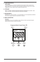
Pressing the MODE key for 3 seconds displays “---”. To return to measurement mode from each setting mode, the “---” display will flash when 3 seconds have passed.
Measurement Mode MODE MODE Press > 3 sec. Press > 3 sec. Select with Function Setting Mode (nP (Comparator operation selection) XW After 1 second Message displayed keys kY5 Hys or !;n kY5 Current setting Hysteresis Win Window comparator Select with MODE XW After 1 second un; (Display selection) Message displayed MODE keys +pa npa Current unit setpoint npa kPa (In SI unit selection) (Only in ETC et( display function selection) MODE d-P .003 etc.
9C. SeleCTING STANDArD Or CUSTOM SCAlING MODe When the et( is selected in “Display Selection”, the display value of Pressure for applied displays as an arbitrary scaling display. This is a function to scale the MIN/MAX display value and has NO effect on applied pressure and analog output. 9D. CUSTOM SCAlING MODe Use the MODE key to set “Decimal point position”, “Minimum pressure range display value” and Maximum pressure range display value” of “Display scaling”.
NOTE: if the switch’s setting value is set outside the display range, the switch’s setting value can be rewritten automatically by the function setting mode operation. Measurement Mode MODE Press < 3 sec. MODE Press > 3 sec. Comparator Setting Mode Loop Check Mode After 1 second (Output1. Comparator setting point A) MODE a-1 50.0 XW Set any desired value within the –1999 to 1999 range with Up/Down keys Message displayed After 1 second (Output1. Comparator setting point b) MODE b-1 10.
11. SwITCh OPerATION – hYSTereSIS/DeADbAND Setting the upper limit. This is the mode in which the switch operates with the setting value (A) as the upper limit. The upper limit setting is determined when you select a positive number (including 0) for setting value (b). Setting the lower limit. This is the mode in which the switch operates with the setting value (A) as the lower limit. The lower limit setting is determined when you select a negative number for setting value (b).
window Comparator Operations loop check function At the end of the Switch Operation Menu is the Loop Check function. Using the MODE key to select the Loop Check function. After lop is displayed for 1 second, the value of the latest measurement mode is displayed as default. Use keys to set displayed value anywhere between –1999 and 1999 to confirm switch operation and/or analog output operation. 12. OTher fUNCTIONS basic key operations In all setting modes, values are set with the keys.
Maximum/Minimum Pressure Capture The GC30 unit keeps the maximum and minimum pressure level applied to the pressure port as peak and bottom values respectively, in the internal memory. The peak and bottom values or keys respectively. Message pe+ is displayed for one are displayed while holding the second and selected Max/Min value is displayed by this operation.
14. MAINTeNANCe AND wArrANTY Periodic Inspection Depending upon the type of use periodic inspection is recommended at least once a year. Please refer to the following items for periodic inspection. 1. Appearance 2. Display/output check via appropriate pressure standard(1) 3. Display/output check via loop Check(2) CAUTION • Avoid electrostatic charging. When cleaning this product, please use a soft, damp cloth. • Do not use thinner, etc. which may cause deterioration and failure.
© 2011 Ashcroft Inc. 250 East Main Street, Stratford, CT 06614 USA Tel: 203-378-8281, Fax: 203-385-0402 www.ashcroft.com All sales subject to standard terms and conditions of sale. I&M011-10169 Rev.