A-SERIES SWITCH SAFETY MANUAL Safety Manual A-Series Pressure Switch Document: I&M009-10210 REV A - Release 4/19/2013 Table of Contents: Section 1. Introduction……………………………………………… 2. Device Description……………………………………… 3. Designing A SIF Using a Manufacturers Product…… 4. Installation and Commissioning……………………….. 5. Operation and Maintenance…………………………… 6. Start-up Checklist………………………………………. I&M009-10210 REV A - 4/19/2013 pg.
A-SERIES SWITCH SAFETY MANUAL 1 INTRODUCTION This Safety Manual provides information necessary to design, install, verify and maintain a Safety Instrumented Function (SIF) utilizing the A-Series pressure switch. This manual provides necessary requirements for meeting the IEC 61508 or IEC 61511 functional safety standards. 1.
A-SERIES SWITCH SAFETY MANUAL 1.2 Acronyms FMEDA Failure Modes, Effects and Diagnostic Analysis HFT Hardware Fault Tolerance MOC Management of Change. These are specific procedures often done when performing any work activities in compliance with government regulatory authorities. PFDavg Average Probability of Failure on Demand SFF Safe Failure Fraction, the fraction of the overall failure rate of a device that results in either a safe fault or a diagnosed unsafe fault.
A-SERIES SWITCH SAFETY MANUAL 1.5 Reference Standards Functional Safety • IEC 61508: 2010 Functional safety of electrical/electronic/ programmable electronic safety-related systems • ANSI/ISA 84.00.01-2004 (IEC 61511 Mod.) Functional Safety – Safety Instrumented Systems for the Process Industry Sector 2 DEVICE DESCRIPTION The A-Series Pressure switch is an electrical switch which is actuated via inlet pressure.
A-SERIES SWITCH SAFETY MANUAL 3.2 Environmental limits The designer of a SIF must check that the product is rated for use within the expected environmental limits. Refer to the temperature limits labeled on the product, or the A-Series pressure switch datasheet available at www.Ashcroft.com. 3.3 Application limits The materials of construction of an A-Series switch are specified in the Ashcroft ASeries pressure switch datasheet.
A-SERIES SWITCH SAFETY MANUAL The product has met manufacturer design process requirements of Safety Integrity Level (SIL) 3. These are intended to achieve sufficient integrity against systematic errors of design by the manufacturer. A Safety Instrumented Function (SIF) designed with this product must not be used at a SIL level higher than the statement without “prior use” justification by end user or diverse technology redundancy in the design. 3.5.
A-SERIES SWITCH SAFETY MANUAL 4 INSTALLATION AND COMMISSIONING 4.1 Installation The A-Series pressure switch must be installed per standard practices outlined in the Installation Manual. The environment must be checked to verify that environmental conditions do not exceed the ratings. The A-Series pressure switch must be accessible for physical inspection. 4.
A-SERIES SWITCH SAFETY MANUAL Table1: Recommended Proof Test Step Action 1 Bypass the safety function and take appropriate action to avoid a false trip. 2 Adjust pressure to the switch and verify that switch trips under designed conditions. 3 Inspect the A-Series pressure switch for any visible damage or contamination. Note that the white housing vent is still in place.
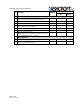
A-SERIES SWITCH SAFETY MANUAL 6 START-UP CHECKLIST The following checklist may be used as a guide to employ the A-Series pressure switch in a safety critical SIF compliant to IEC61508.
A-SERIES SWITCH SAFETY MANUAL # Activity Verification and Testing Electrical connections verified and tested Pneumatic connection verified and tested SIS logic solver valve actuation test verified Safety loop function verified Safety loop timing measured Bypass function tested Verification and test results formally reviewed and suitability formally assessed Maintenance Tubing blockage / partial blockage tested Safety loop function tested I&M009-10210 REV A - 4/19/2013 Result Verified By Date