
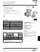
Product Overview

304
Visit our website at ASCO.com or contact us at (800) 972-2726
2/2
SERIES
S262
COMBUSTION
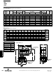
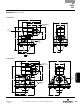
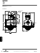
Dimensions inches (mm)
Specifications English units (Metric)
Vent Valve Requirements
Manifold Line Vent Valve
3/8" through 1-1/2"
3/4
2"
1
2-1/2" through 3" 1-1/4
3-1/2"
1-1/2
4" through 5" 2
5-1/2" through 6" 2-1/2
6-1/2" through 7-1/2"
3
Const. Ref. 1, 2
P
ipe
S
ize
in
O
rifice
S
ize
in (mm)
F
low
F
actor
Cv (Kv)
Gas
C
apacity ¨
O
perating Pressure
D
ifferential psi (bar)
M
ax.
F
luid
T
emp.
˚F (˚C)
C
atalog Number
C
onst.
Ref.
A
gency
Wattage
A
pprox.
S
hipping
W
eight
lbs (kgs)
Btu/hr. Min. Max. 24/60 120/60 240/60 UL FM CSA
C
OMBUSTION (Fuel Gas) - NORMALLY OPEN
3
/8"
3
/4" (19)
3
.5 (3.0)
1
91,000
0 3
0 (2.1)
1
40 (60)
S
262SH01N3CG5
S
262SH02N3CG5
S
262SH04N3CG5
1
l l l
1
0.5
1
.5 (0.7)
1/2" 3/4" (19) 4.0 (3.5) 210,300 0 30 (2.1) 140 (60)
S262SH01N3DG5 S262SH02N3DG5 S262SH04N3DG5
1
l l l
10.5 1.5 (0.7)
3
/4"
3
/4" (19)
4
.7 (4.1)
2
52,000
0 3
0 (2.1)
1
40 (60)
S
262SH01N3EG5
S
262SH02N3EG5
S
262SH04N3EG5
2
l l l
1
0.5
1
.7 (0.8)
1" 1-5/8" (41) 19.8 (17.1) 1,068,000 0 25 (1.7) 140 (60)
S262SH01N3FJ5 S262SH02N3FJ5 S262SH04N3FJ5
3
l l l
15.4 2.9 (1.3)
1
-1/4"
1
-5/8" (41)
3
4 (29)
1
,941,100
0 2
5 (1.7)
1
40 (60)
S
262SH01N3GJ7
S
262SH02N3GJ7
S
262SH04N3GJ7
4
l l l
1
5.4
4
.0 (1.8)
1-1/2" 1-5/8" (41) 37 (32) 2,157,000 0 25 (1.7) 140 (60)
S262SH01N3HJ7 S262SH02N3HJ7 S262SH04N3HJ7
4
l l l
15.4 3.7 (1.7)
2
"
3
" (76)
8
4 (73)
4
,529,300
0 1
5 (1.0)
1
40 (60)
- S
262SH02N3JK4
S
262SH04N3JK4
5
l l l
2
8.2
1
3.5 (6.2)
2-1/2" 3" (76) 123 (106) 6,632,200 0 15 (1.0) 140 (60)
- S262SH02N3KK4 S262SH04N3KK4
5
l l l
28.2 13.0 (5.9)
3
"
3
" (76)
1
32 (114)
7
,118,000
0 1
5 (1.0)
1
40 (60)
- S
262SH02N3LK4
S
262SH04N3LK4
5
l l l
2
8.2
1
2.5 (5.7)
l = General Purpose Valve. ¨ 1” W.C. Drop @ 2” W.C. Inlet Pressure, 1,000 Btu/cu.ft. or more, 0.64 Specific Gravity Gas.
Const.
Ref.
A B H J K L M N P R T W
Mounting
Position
1
in
1.14 4.00 4.36 3.11 2.67 2.75 2.06 4.48 3.78 1.37 1.86 2.45
Above
Horizontal
mm
29 101 111 79 68 70 52 114 96 35 47 62
2
in
1.14 4.00 4.78 3.11 2.86 3.31 2.06 4.77 3.97 1.66 1.86 2.33
Above
Horizontal
mm
29 101 122 79 73 84 52 121 101 42 47 59
3
in
1.9 4.6 6.1 3.5 1.8 4.01 2.5 5.8 3.2 2.3 2.2 3.8
Vertical &
Upright
mm
48 118 155 90 47 102 63 149 80 58 56 95
4
in
2.69 4.63 6.74 3.54 2.12 5 2.5 6.2 3.46 2.62 2.2 5.4
Vertical &
Upright
mm
68 118 171 90 54 127 63 156 88 66 56 137
5
in
3.82 5.8 10.4 4 3 7.8 3 8 5.3 3.9 3.3 7.9
Vertical &
Upright
mm
97 147 264 105 78 198 78 204 134 99 84 202
M
J
T
H
P
K
L
W
B
N
R
A
N
ANPT PIPE THREAD
BOTH ENDS
(SEE TABLE)
FLOW
P
Ø .87 [22.2] KNOCKOUTS
FOR CONDUIT CONNECTION
BOTH SIDES
PIPE TAPS
ANPT 1/8" PLUG
2 PLACES