
Install Instructions

50 Hanover Road, Florham Park, New Jersey 07932 www.ascovalve.com
Page 2 of 4 I&M No.V8500R3
CAUTION: To protect the solenoid valve, install a
strainer or filter, suitable for the service involved, in the
inlet side as close to the valve as possible. Clean
periodically depending on service conditions. See
ASCO Series 8600, 8601 and 8602 for strainers.
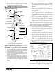
Wiring
Wiring must comply with local codes and the National
Electrical Code. To facilitate wiring, the solenoid enclosure
may be rotated 360_. The junction box housing has two 7/8I
diameter knockouts to accommodate 1/2I conduit. Drive out
appropriate knockout with junction box completely assembled
(with cover) for support. Remove J" box cover, by spreading
cover and disengaging nibs (lift up and pull down
simultaneously) . The junction box is provided with a
grounding screw (green) and a hole in the yoke for the
grounding connection. Within the junction box solenoid
enclosure use field wire that is rated 125_ C or greater for
connections. Replace J" box cover before operating.
Testing for External Leakage
WARNING: To prevent the possibility of death,
serious injury or property damage, extinguish all open
flames and avoid any type of sparking or ignition.
1. Block gas flow on downstream side of valve.
2. Apply pressure to valve within nameplate rating and
energize solenoid.
3. Apply a soapy solution or a commercially available leak
detecting solution to the pipe connections and check for
bubbles. If the valve has been tested for seat leakage,
apply the solution around the pipe plugs.
4. If leakage exists, depressurize valve and turn off
electrical power supply. Tighten connections as required
and retest following the above steps.
Solenoid Temperature
Series K3A4 and K3A5 valves are supplied with coils designed
for continuous duty service. When the solenoid is energized
for a long period, the solenoid enclosure becomes hot and can
be touched with the hand for an instant. This is a safe operating
temperature. Any excessive heating will be indicated by the
smoke and odor of burning coil insulation.
MAINTENANCE
WARNING: To prevent the possibility of death,
serious injury or property damage, turn off electrical
power, depressurize valve, extinguish all open flames
and avoid any type of sparking or ignition. Vent
hazardous or combustible fluid to a safe area before
inspection or removing the valve from service.
Preventive Maintenance
S Keep medium flowing through the valve as free from dirt
and foreign material as possible.
S Periodic exercise of the valve should be considered if
ambient or fluid conditions are such that corrosion,
elastomer degradation, fluid contamination build up, or
other conditions that could impede solenoid valve shifting
are possible. The actual frequency of exercise necessary will
depend on specific operating conditions. A successful
operating history is the best indication of a proper interval
between exercise cycles.
S Depending on the medium and service conditions, periodic
inspection of internal valve parts for damage or excessive wear
is recommended.
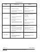
NOTE: For performance problems, refer to Troubleshooting
Chart on page 4 of 4.
Coil Replacement (Refer to Figure 2)
NOTE: It is not necessary to remove the valve from the
pipeline for Coil Replacement.
CAUTION: Exercise care to prevent damage to the
solenoid base sub-assembly. Do not grasp solenoid
base sub-assembly with wrench or pliers.
1. Disconnect supply wires to coil and rigid conduit from
junction box.
2. Remove retaining clip and flat washer from top of
solenoid.
CAUTION: When metal retaining clip disengages,
it will spring upward.
3. Remove J" box cover by spreading cover and
disengaging nibs (lift up and pull down simultaneously)
4. Slip housing assembly containing yoke and coil off
solenoid base sub-assembly.
5. Coil is now accessible for replacement.
6. Reassembly in reverse order of disassembly using a new
coil replacement.
7. Make electrical connections to solenoid, see Wiring
section.
Valve Disassembly (Refer to Figure 2)
1. Disassemble valve in an orderly fashion. Paying careful
attention to exploded view for identification and
placement of parts. See Figure 2.
2. Remove retaining clip from top of solenoid and remove
solenoid enclosure. If rigid conduit is used, remove J"
box cover by lifting up and pulling down on cover
simultaneously. Disconnect conduit, grounding wire and
supply wires to coil.
CAUTION: When metal retaining clip disengages,
it will spring upward.
3. Remove bonnet screws and lift valve bonnet off valve.
4. Parts are now accessible for inspection, cleaning or
replacement. If parts are worn or damaged, replace
valve.
Valve Reassembly
1. Position valve bonnet onto valve body.
2. Hand thread bonnet screws into valve body as far as
possible. Then torque bonnet screws in a crisscross
manner to 10-13 in-lbs [1,1-1,5 Nm] for 3/8I, 1/2I
& 3/4I ANPT only. On 1I ANPT only, torque bonnet
screws to 18-21 in-lbs [2,0-2,4 Nm].
3. Install solenoid. Install retaining clip.
4. Restore electrical power supply to valve.