
Install Instructions

50 Hanover Road, Florham Park, New Jersey 07932 www.ascovalve.com
Page 3 of 4I&M No.V8500R3
5. After maintenance is completed, operate the valve a
few times to be sure of proper operation. A metallic
click indicates the solenoid is operating.
CAUTION: Solenoid must be fully reassembled
because the housing and internal parts are part of and
complete the magnetic circuit.
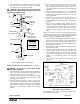
Figure 2. Exploded view, typical K3A valve.
coil
retaining clip
housing
valve bonnet
J-box
cover
solenoid base
sub-assembly
flat washer
nameplate
spring washer
grounding
screw
cup washer
yoke
valve body
core
assembly
bonnet screw
(see chart below)
1I ANPT
[2,0-2,4 Nm]
3/8I, 1/2I, 3/4I ANPT
18-21 in-lbs
[1,1-1,5 Nm]
10-13 in-lbs
Torque bonnet screw
gasket
Testing for Internal (Seat) Leakage (Refer to Figure 3)
CAUTION: Be sure valve can be tested without
affecting other equipment.
1. Shut off both the upstream and downstream manual gas
cocks. The downstream manual gas cock should remain
closed throughout the entire test procedure.
2. Program the control system to operate the valve through
five cycles. Listen carefully for the solenoid coil to click
indicating proper operation.
3. Open the upstream manual gas cock. Program the
control system to energize and maintain the valve in the
open (energized) position. Check all valve and piping
connections for external leaks with rich soap and water
solution or a commercially available leak detecting
solution.
4. Shut off the upstream manual gas cock and de-energize
valve. Remove the plug from the leak test tap or
downstream pressure tap in the valve body. Connect leak
test equipment with the test petcock in the closed position
(Figure 3).
5. Open the upstream manual gas cock. Program the
control system to energize the valve to the full open
position, then immediately de-energize it to seat the
valve operationally.
6. Immerse the 1/4I leak test tube vertically into a jar of
water to a depth of about 1/2I. Slowly open the test
petcock. Bubbles may appear in the water as the pressure
equalizes.
7. After the rate of bubbles coming through the water
stabilizes, count the number of bubbles appearing in a 10
second period. The allowable leakage in 10 seconds for
an orifice diameter of 1 inch (25.4 mm) or less is 6
bubbles (3 cc/min). If leakage exceeds this rate, replace
valve.
NOTE: The leakage rate above recognizes that some wear
and contamination from use can result in a slight amount of
leakage. The allowable leakage rate is well within the leakage
limits as recognized by applicable approval agencies.
8. Close the upstream manual gas cock and the test petcock.
Then remove the test equipment. Apply a small amount
of Loctite Corporation's PSTr Pipe Sealant 567 (or
equivalent) to the pipe plug threads. Reinstall the pipe
plug and tighten securely.
9. Turn on the gas supply at the upstream manual gas cock
and energize the valve.
10. Open the upstream manual gas cock. Program the
control system to energize and maintain the valve in the
open (energized) position. Check all valve and piping
connections for external leaks with rich soap and water
solution or a commercially available leak detecting
solution.
11. De-energize the valve. Open the downstream manual
gas cock.
12. Restore the system to normal operation.
Figure 3. Testing for internal seat leakage.
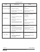
ORDERING INFORMATION
FOR COIL REPLACEMENT
When ordering coils, specify valve catalog number, voltage
and coil number, if possible.