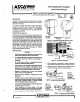
ASCOT 50-60 Hanover Rd, Floral Park, NJ 07932 H10 Hydramotor® Actuator Travel Limit, Pull-Type INSTALLATION AND SERVICE SDI: H10-3 DESCRIPTION Hydramotor® valves consist of three components: the actuator described in this sheet (Figure 1) together with a mounting yoke and a valve body. H10 hydraulic actuators pull when energized and extend, powered by an internal return spring, when energized, providing ON-OFF control of valves.
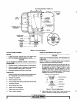
ACTUATOR ASSEMBLY NAMEPLATE Py [ 2 fr—ra—— FILLER PLUG Va: POWER 7] UNIT LMT CYLINDER SWITCH -S 1 ASSEMBLY “0” RING d © PLATE (2 RED) p PACKING RING 2 RED) TERMINAL PLATE ASSEMBLY > = NIPPLE T TRAVEL LIMIT PUSH ROD YOKE rer] INDICATOR PLATE P UNION PLATE 12 WAVE STEM Figure 5. H10 Cross Section ACTUATOR REPLACEMENT STEM NUT ADJUSTMENT (See Figure 6) 1. Loosen lock screw, unscrew union nut to detach valve stem from actuator shaft (see Figures 5 and 6).
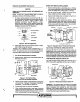
STEM NUT ADJUSTMENT (See Figure 8) CAUTION i stem nut is not adjusted property, valve assembly may mat unction. NOTE: if stem nut is removed during repair, it must be adjusted according to the following procedure. 1. For proper seating pressure and correct valve ft, dis. stance from bottom of actuator shaft to top of stem nutritious be measured, as shown in Figure 6 {refer io valve installation instructions).
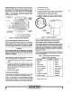
Adjustment {Figure 10): Each switch in auxiliary switch unit may be adjusted separately to actuate at any point of actuator stem travel. Turn individual switch adjustment screw counterclockwise to actuate switch closer to energized position. Turn screw only at a ime and check operation. De not attempt to set switch for operation within 1/8" of either end of stroke. PROOF OF-CLOSURE AUXILIARY SWITCHES 0 SWITCH BOX ~~ {COVER REMOVED) A — NO. when actuator energized Bw N.C. when actuator energized Figure 10.