
Install Instructions

Page 3 of 4
©ASCO Valve, Inc.® 50 Hanover Road, Florham Park, New Jersey 07932 www.ascovalve.com
I&M No. V 8860 R2
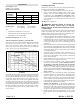
Optional
Auxiliary and Overtravel Proof-of-Closure
Switch Combinations (Partial Views)
N or L2
Connect neutral
to terminal 1 if
applicable
Proof of
closure
or
auxiliary
switch
NO
NC
C
Limit Switch Wiring
Figure 2
Ground screws
L1
Connect
to power
Travel limit switch
Do Not Adjust
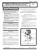
Auxiliary and Overtravel Proof-of-Closure
Switch Ratings
120VAC: 15 Amps, 1/3 HP
240VAC: 7.5 Amps, 1/2 HP
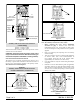
Aux. Left side Aux. Right side
Two Auxiliary Switches
Figure 3
Single Auxiliary Switch
Figure 4
Auxiliary
Proof-of-Closure
Proof-of-Closure Switch
Figure 5
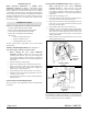
Adjust
this
screw
Auxiliary Switch Adjustment
Figure 6
Total connected load of auxiliary and overtravel proof-of -closure
switches not to exceed 1800VA.
CAUTION: Overtravel Proof-of-closure switch must
only be used with V710 Series Gas Valves having an
overtravel seal (V22 or V25 Suffi x in catalog number).
Overtravel Proof-of-Closure Switch
The optional valve overtravel proof-of-closure switch is set at
the factory to provide both a mechanical and electrical means of
proving valve closed position interlock to the primary control.
This switch is not to be fi eld adjusted.
Auxiliary Switch Adjustment (Refer to Figure 6)
Note: The Auxiliary switch is not a safety switch.
1. Before removing the cover, review WARNING
statements on page 1. Remove cover screws and
nameplate/electrical cover (with gasket if fi tted). Take
care not to damage the sealing surfaces and cover gasket if
supplied.
2. Insert 1/16” Allen key into adjusting screw on auxiliary
switch assembly.
3. Turn screw clockwise to move set point towards beginning
of actuator stroke. Turn screw counterclockwise to
move setpoint toward the end of the actuator stroke.
(approximately 8.5 turns from 0 to 100% travel)
4. Cycle the actuator to verify the switch setting and readjust
as required.
5. Install the cover. Be certain that the gasket (if applicable)
and sealing surfaces are clean and without damage. Snug
down all screws before tightening. Torque screws 20 to
25 in-lbs (2.3 to 2.8 Nm) evenly using a crisscross pattern
starting in the middle.