
Install Instructions


Page 4 of 4
©ASCO Valve, Inc.® 50 Hanover Road, Florham Park, New Jersey 07932 www.ascovalve.com
I&M No. V 8860 R2
Field Service Notice
Field service replacement kits are limited to the following:
1. Auxiliary Switch Replacement Kit 296804.
2. Proof of Closure Switch Replacement Kit 296806.
3. Travel Limit Switch Replacement Kit 296807.
4. Gasket and Screw Replacement Kit 296808.
Kit contains:
• Front cover gasket and screws
• Window o-ring and screws
• Mounting gasket and set screws.
To order, specify the kit or part number, as well as the actuator
model number.
Auxiliary Switch Replacement (Refer to Figure 7)
Note: The Auxiliary switch is not a safety switch.
1. Before removing the cover, review WARNING
statements on page 1. Remove the front cover (with
nameplate) and set aside. Take care not to damage the
cover gasket if supplied or sealing surfaces. A diagram is
located on the inside of the cover to aid in making electrical
connections.
2. Disconnect auxiliary switch wiring.
3. Remove two mounting screws and the auxiliary switch.
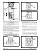
4. Install new auxiliary switch in the actuator making sure
that the fork of the switch actuation lever engages the
indicator arm as shown in Figure 8.
5. Torque mounting screws 20 to 25 in-lbs (2.3 to 2.8 Nm).
6. Reconnect switch wiring and torque terminal screws 8 to
12 in-lbs (0.9 to 1.3 Nm).
7. See instructions on page 3 for auxiliary switch adjustment,
starting at Step 2.
Proof of Closure Switch Replacement
Same as auxiliary switch replacement except switch must NOT
be adjusted.
Auxiliary Switch
Figure 7
Fork must
engage arm
as shown
Do not adjust
this screw
Limit Switch
Figure 8
MAINTENANCE
Before inspection, maintenance or rebuild, review
WARNING statements on page 1. Maintenance should
include annual inspection and cleaning. Use a mild cleaning
fl uid, not aggressive solvents to remove dirt and oil. Organize
a maintenance schedule based on environment and frequency
of use. Check for loose electrical and mechanical connections
and replace damaged parts. Do not remove the top cover for
maintenance. There are no serviceable parts contained inside
the actuator housing.
Travel Limit Switch Replacement (Refer to Figure 8)
1. Before removing the cover, review WARNING
statements on page 1. Remove the front cover (with
nameplate) and set aside. Take care not to damage the
cover gasket if supplied or sealing surfaces. A diagram is
located on the inside of the cover to aid in making electrical
connections.
2. Remove the two mounting screws.
3. Disconnect wiring from the travel limit switch taking care
not to strain the wire connection at the terminal.
4. Install new travel limit switch. Torque mounting screws 20
to 25 in-lbs (2.3 to 2.8 Nm). Travel limit switches are set at
the factory. DO NOT adjust.
5. Plug terminal connections to travel limit switch.
6. Install the cover. Be certain that the gasket (if applicable)
and sealing surfaces are clean and without damage. Snug
down all screws before tightening. Torque screws 20 to
25 in-lbs (2.3 to 2.8 Nm) evenly using a crisscross pattern
starting at the middle.
7. Operate actuator (with valve) through fi ve cycles to verify
proper operation prior to use.
Gasket replacement
The gaskets have an adhesive attachment. Use a nonmarring tool
to peel off the old gasket. Remove backing from new gasket and
stick on in the same location as the old gasket.