
Install Instructions


50 Hanover Road, Florham Park, New Jersey 07932 www.ascovalve.com
Page 4 of 4 Form No.V5256R9
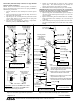
Disassembly and Reassembly of Stem /Lever Type Manual
Operator (Refer to Figure 3)
NOTE: There are two stem/lever manual operator constructions.
They are identified by the location of the core spring as internal or
external spring construction.
1. Unscrew solenoid base sub-assembly from manual operator
body.
2. Unscrew manual operator body from valve body. Then remove
body gasket and stem retainer.
3. Slip stem/spacer sub-assembly with stem gasket from manual
operator body. Remove core assembly with core spring from
center of manual operator body.
4. All parts are now accessible for cleaning or replacement.
Lubricate gaskets per Valve Reassembly step 2.
5. Position core assembly with core spring into base of manual
operator body. Then install stem/spacer sub-assembly into
manual operator body to engage with core assembly.
6. Reinstall stem retainer on body and stem/spacer sub-assembly.
IMPORTANT: The spacer on the stem/spacer sub-assembly must
be inside of the stem retainer for internal spring construction and
outside the stem retainer for external spring construction.
7. Replace body gasket and install manual operator assembly in
valve body. Torque manual operator body to 175 ± 25 in-lbs
[19,8 ± 2,8 Nm].
8. Replace solenoid base gasket and solenoid base sub-assembly.
Torque solenoid base sub-assembly to 175 ± 25 in-lbs [19,8
± 2,8 Nm].
9. Check manual operator for proper operation. Turn stem clockĆ
wise and counterclockwise; stem should turn freely without
binding.
solenoid base
core assembly
core spring
solenoid base
manual
body gasket
stem/spacer
stem
core spring
stem retainer
valve body
Note:
Indicates Parts Supplied
In ASCO Rebuild Kits
Internal Spring
Construction
External Spring
Construction
sub-assembly
(see note)
gasket
sub-assembly
operator
body
gasket
External
Internal
spacer
stem retainer
Spacer location for
spacer
Spacer location for
external spring
construction
internal spring
construction
valve body
solenoid base
sub-assembly
core spring
core assembly
body gasket
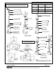
end cap
disc spring
disc holder assembly
body gasket
(see note 2)
(see note 3)
(Port 3 plugged)
1/4 NPT-Brass
plugnut/core tube
sub-assembly
core spring
core assembly
body gasket
valve body
mounting bracket
disc
end cap
disc spring
disc holder assembly
body gasket
bonnet gasket
optional feature
(see note 1)
(Port 3 plugged)
(see note 2)
(see note 3)
valve bonnet
1/8 NPT-Stainless Steel
(see note 4)
mounting bracket
(optional feature)
4 positions
2 self-tapping
screws provided
Notes:
1.
2.
3.
4.
For mounting, a flat surface must be provided
across the entire length of the bracket. The
valve body becomes secure to bracket when
bracket is tightened into position.
Body inverted for in-line piping. Inverted 1 is
valve inlet and inverted 2 is valve outlet.
Wide end of core spring in core first, closed
end protrudes from top of core.
Bonnet wrench supplied in ASCO Rebuild Kit.
For bonnet wrench only order No. K218948.
Important: Spacer must be inside of stem retainer
for internal spring construction and outside of stem
retainer for external spring construction.
Wide end of core spring in core first, closed
end protrudes from top of core.
Indicates Parts Supplied
In ASCO Rebuild Kits
stem gasket
Figure 3. Stem/lever type manual operators Figure 4. Series 8262, normally open construction.