
Install Instructions


Page 1 of 4
50 Hanover Road, Florham Park, New Jersey 07932 www.ascovalve.com
MM All Rights Reserved.
Printed in U.S.A.
Installation & Maintenance Instructions
SERIES
Form No.V5256R9
2-WAY DIRECT-ACTING SOLENOID VALVES
BRASS OR STAINLESS STEEL CONSTRUCTION - 1/8, 1/4, OR 3/8 NPT
8262
8263
NORMALLY OPEN OR NORMALLY CLOSED OPERATION
IMPORTANT: See separate solenoid installation and maintenance
instructions for information on: Wiring, Solenoid Temperature,
Causes of Improper Operation, and Coil or Solenoid Replacement.
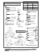
DESCRIPTION
Series 8262 and 8263 valves are 2-way direct-acting general service
solenoid valves. Valves bodies are of rugged brass or stainless steel.
Series 8262 or 8263 valves may be provided with a general purpose or
explosionproof solenoid enclosure. Series 8262 and 8263 valves with
suffix P" in the catalog number are designed for dry inert gas and
non-lubricated air service.
OPERATION
Normally Open: Valve is open when solenoid is de-energized; closed
when is energized.
Normally Closed: Valve is closed when solenoid is de-energized;
open when energized.
IMPORTANT: No minimum operating pressure required.
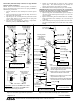
Manual Operation
Manual operator allows manual operation when desired or during an
electrical power outage. Depending upon basic valve construction,
three types of manual operators are available:
Push Type Manual Operator
To engage push type manual operator, push stem at base of valve body
upward as far as possible. Valve will now be in the same position as
when the solenoid is energized. To disengage manual operator, reĆ
lease stem. Manual operator will return to original position.
Screw Type Manual Operator
To engage screw type manual operator, rotate stem at base of the
valve body clockwise until it hits a stop. Valve will now be in the same
position as when the solenoid is energized. To disengage, rotate stem
counterclockwise until it hits a stop.
CAUTION: For valve to operate electrically, manual operator
stem must be fully rotated counterclockwise.
Stem/Lever Type Manual Operator
To engage manual operator, turn stem/lever clockwise until it hits a
stop. Valve will now be in the same position as when the solenoid is
energized. To disengage manual operator, turn stem/lever counterĆ
clockwise until it hits a stop.
CAUTION: For valve to operate electrically, manual operator
stem/lever must be fully rotated counterclockwise.
Flow Metering Devices
Valves with suffix M" in catalog number are provided with a meterĆ
ing device for flow control. Turn stem to right to reduce flow; left to
increase flow.
INSTALLATION
Check nameplate for correct catalog number, pressure, voltage,
frequency, and service. Never apply incompatible fluids or exceed
pressure rating of the valve. Installation and valve maintenance to be
performed by qualified personnel.
Note: Inlet port will either be marked I" or IN". Outlet port will be
marked 2" or OUT".
Future Service Considerations.
Provision should be made for performing seat leakage, external leakĆ
age, and operational tests on the valve with a nonhazardous,noncomĆ
bustible fluid after disassembly and reassembly.
Temperature Limitations
For maximum valve ambient and fluid temperatures, refer to charts
below. Check catalog number, coil prefix, suffix, and watt rating on
nameplate to determine the maximum temperatures.
Wattage
Catalog
Number
Coil
Prefix
Coil
Class
Max.
Ambient
Temp. F
Max.
Fluid
Temp. F
6, 10.5,
12.4
none,ĂDA or
S
A 77 180
6,10.5
12.4
DF, FT
or SF
F 125 180
6,10.5,
12.4
HT H 140 180
9,10.7
none, DP or
SP
F 77 180
9.7
none, FT or
HT
A, F
or H
77 120
11.2
none, FT or
HT
A, F
or H
77 150
16.7
none, DP or
SP
F 77 200
17.1
none, KP
SP or SD
F 125 180
17.1
HB, KB SS
or SV
H 140 180
Catalog Nos.8262B200 and 8262 C200 AC construction only and
Catalog Nos.8262B214 and 8262 D200 AC and DC construction are
limited to 140F fluid temperature.
Valves with Suffix V or W that are designed for AC service and norĆ
mally closed operation are for use with No. 2 and 4 fuel oil service.
These valves have the same maximum temperatures per the above
table except Suffix W valves are limited to a maximum fluid temperaĆ
ture of 140F.
Listed below are valves with Suffix V in the catalog number that are
acceptable for higher temperatures.
Catalog Number
Coil Prefix
Max. Ambient
Temp.F
Max. Fluid
Temp.F
FT8262, HB8262
FT8263, HB8263
8262G, 8263G
125 250*
HT or HB 8262G
HT or HB 8263G
140 250
*The only exception is the 8262G and 8263G series (Class F coil) at 50
Hertz rated 11.1 and 17.1 watts are limited to 210F fluid temperature.
Positioning
This valve is designed to perform properly when mounted in any posiĆ
tion. However, for optimum life and performance, the solenoid
should be mounted vertically and upright to reduce the possibility of
foreign matter accumulating in the solenoid base sub-assembly area.