
Install Instructions

Page 1 of 4
50-60 Hanover Road, Florham Park, New Jersey 07932
ASCO Valves
MCMXCV All Rights Reserved.
Printed in U.S.A.
Installation & Maintenance Instructions
SERIES
Form No.V5452R3
2-WAY INTERNAL PILOT-OPERATED SOLENOID VALVES
8222
NORMALLY CLOSED OPERATION Ċ STEAM SERVICE
3/8, 1/2 OR 3/4 NPT
NOTICE: See separate solenoid installation and
maintenance instructions for information on: Wiring,
Solenoid Temperature, Cause of Improper Operation and
Coil Replacement.
DESCRIPTION
Series 8222 valves are 2-way normally closed, internal
pilot-operated solenoid valves designed for steam service.
Valves are made of rugged brass or stainless steel with
internal parts of stainless steel and elastomers of ethylene
propylene. Series 8222 valves may be provided with a
general purpose or explosionproof solenoid enclosure.
OPERATION
Normally Closed: Valve is closed when solenoid is
de- energized; open when energized.
NOTE: No minimum operating pressure differential
required.
Manual Operator (optional feature)
Manual operator allows manual operation when desired or
during an electrical power outage. To engage manual
operator (open the valve), turn stem clockwise until it hits
a stop. Valve will now be in the same position as when the
solenoid is energized. To disengage manual operator (close
the valve), turn stem counterclockwise until it hits a stop.
CAUTION: For valve to operate electrically, manual
operator stem must be fully rotated counterclockwise.
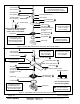
Relocation of Manual Operator
WARNING: To prevent the possibility of
personal injury or property damage, turn off
electrical power, depressurize valve, and
vent fluid to a safe area before relocating
manual operator.
Manual operator may be relocated at 90 increments by
rotating the valve bonnet as follows:
1. See separate solenoid installation and maintenance
instruction's and follow instructions to loosen solenoid
to allow rotation of enclosure.
2. Be sure manual operator stem is counterclockwise.
3. Remove bonnet screws from valve body.
4. Lift valve bonnet slightly and rotate to desired position.
Do not rotate the diaphragm assembly with the valve
bonnet.
5. Replace bonnet screws and torque in a crisscross
manner to 50 ± 5 in-lbs [5,7 ± 0,6 Nm].
6. Position and tighten solenoid in place, see separate
instructions.
WARNING: To prevent the possibility of
personal injury or property damage, check
valve for proper operation before returning to
service.
7. Test operate valve electrically and manually. Be sure
valve can be test operated without effecting other
equipment.
8. Restore line pressure and electrical power supply to
valve.
INSTALLATION
Check nameplate for correct catalog number, pressure,
voltage, frequency, and service. Never apply incompatible
fluids or exceed pressure rating of the valve. Installation and
valve maintenance to be performed by qualified personnel.
Future Service Considerations
Provision should be made for performing seat leakage,
external leakage, and operational tests on the valve with a
nonhazardous, noncombustible fluid after disassembly and
reassembly.
IMPORTANT: Maximum operating pressure differentials
are based on temperature-related material limitations.
Therefore, do not use valves with a steam source of higher
pressure than the nameplate maximum operating pressure
differential. Also do not use a pressure reducing valve to
reduce steam source to rated pressure because this would
result in superheated steam of excessive temperature
entering the valve.
Temperature Limitations And Pressure Ratings
For maximum valve ambient and fluid temperatures, refer
to chart below.
Maximum Pressure
Rating psi & service
(Maximum Operating
Pressure Differential)
Coil
Class
Max.
Ambient
Temp.F
Max.
Fluid
Temp.F
50 steam
F
or
H
77 300
Positioning
This valve is designed to perform properly when mounted in
any position. However, for optimum life and performance,
the solenoid should be mounted vertically and upright to
reduce the possibility of foreign matter accumulating in the
solenoid base sub-assembly area.
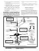
Mounting
For mounting bracket (optional feature) dimensions, refer
to Figure 1.