
User Guide

50-60 Hanover Road, Florham Park, New Jersey 07932
ASCO Valves
Page 2 of 4 Form No.V6493R3
Cleaning
All solenoid valves should be cleaned periodically. The time
between cleanings will vary depending on the medium and
service conditions. In general, if the voltage to the coil is
correct, sluggish valve operation, excessive noise or leakage
will indicate that cleaning is required. In the extreme case,
faulty valve operation will occur and the valve may fail to
open or close. Clean strainer or filter when cleaning the
valve.
Preventive Maintenance
Keep the medium flowing through the valve as free from
dirt and foreign material as possible.
While in service, the valve should be operated at least
once a month to insure proper opening and closing.
Depending on the medium and service conditions,
periodic inspection of internal valve parts for damage or
excessive wear is recommended. Thoroughly clean all
parts. If parts are worn or damaged, install a complete
ASCO Rebuild Kit.
Causes of Improper Operation
Incorrect Pressure: Check valve pressure. Pressure to
valve must be within range specified on nameplate.
Excessive Leakage: Disassemble valve and clean all parts.
If parts are worn or damaged, install a complete ASCO
Rebuild Kit.
Valve Disassembly
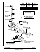
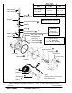
Note: Refer to Figure 1 for 1, 1 1/4 or 1 1/2 NPT valve
constructions. Refer to Figure 2 for 2 or 2 1/2 NPT, Suffix
HW valve constructions.
1. Disassemble valve in an orderly fashion using exploded
views for identification of parts.
2. Remove solenoid, see separate instructions.
CAUTION: Do not remove body plug on 2 or 2
1/2 NPT valves. The body plug has been sealed in
place at the factory. Removal is not necessary for
cleaning or rebuilding.
3. Unscrew solenoid base sub-assembly with special
wrench adapter supplied in ASCO Rebuild Kit. For
wrench only, order ASCO Wrench Kit No. K218950.
4. Remove solenoid base sub-assembly, core, plugnut
assembly, and solenoid base gasket. On suffix HW"
valve constructions, remove stem.
5. Unscrew adapter and remove disc holder assembly,
disc holder spring, and adapter gasket.
6. For normal maintenance (cleaning), it is not necessary
to remove the valve seat. However, for valve seat
removal use a 7/16 thin wall socket wrench.
7. Remove bonnet screws and valve bonnet from valve
body. Then remove the following parts:
Piston Spring Disc Bleed gasket
Lip Seal Aspirator tube Bleed washer
Support Snubber Flow control
Piston Body gasket Lower bleed
washer
Present on 2 & 2 1/2 NPT valve constructions only.
8. All parts are now accessible to clean or replace.
Replace worn or damaged parts with a complete ASCO
Rebuild kit.
Valve Reassembly
1. Reassemble using exploded views for identification
and placement of parts.
2. Lubricate the disc and all gaskets with DOW
CORNING 111 Compound lubricant or an
equivalent high-grade silicone grease.
3. On 2 or 2 1/2 NPT valve constructions, install lower
bleed washer (small diameter) into valve body. Then
position the flow control into valve body with concave
end outward; facing the valve bonnet. Position bleed
washer and gasket over the flow control.
4. Preassemble aspirator tube (2 or 2 1/2 NPT
construction only), snubber, disc, and piston.
5. Position lip seal, flanged end up, onto piston. Position
body gasket and support in valve body cavity. Install
piston with snubber, disc, and lip seal into support in
valve body cavity.
6. Replace piston spring, valve bonnet and bonnet screws.
Torque bonnet screws in a crisscross manner to 144 ±
15 in-lbs [16,3 ± 1,7 Nm].
7. If removed, replace seat with a small amount of thread
compound on male threads to avoid possible leakage.
Torque valve seat to 65 ± 15 in-lbs [7,3 ± 1,7 Nm].
8. Replace disc holder spring, disc holder assembly, stem
(suffix HW" valves only), adapter gasket, and
adapter. Torque adapter to 175 ± 25 in-lbs [19,8 ± 2,8
Nm].
9. Replace solenoid base gasket, plugnut assembly, core
with small end up and solenoid base sub-assembly.
Torque solenoid base sub-assembly to 175 ± 25 in-lbs
[19,8 ± 2,8 Nm].
10. Install solenoid, see separate instructions. Then make
electrical hookup to solenoid.
WARNING: To prevent the possibility of
death, serious injury or property damage,
check valve for proper operation before
returning to service. Also perform internal
seat and external leakage tests with a
nonhazardous, noncombustible fluid.
11. Restore line pressure and electrical power supply to
valve.
12. After maintenance is completed, operator the valve a
few times to be sure of proper operation. A metallic
click signifies the solenoid is operating.
ORDERING INFORMATION
FOR ASCO REBUILD KITS
Parts marked with an asterisk (*) in the exploded view are
supplied in Rebuild Kits. When Ordering Rebuild Kits for
ASCO valves, order the Rebuild Kit number stamped on the
valve nameplate. If the number of the kit is not visible, order
by indicating the number of kits required, and the Catalog
Number and Serial Number of the valve(s) for which they
are intended.