
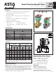
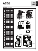
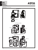
Submittal Sheet

2/2
SERIES
8210
4
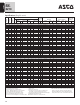
2-WAY
13
Pipe
Size
(
in)
Orifice
Size
(
mm)
K
v Flow
Factor
(
m
3
/hr)
O
perating Pressure Differential (bar)
M
ax.
Fluid
Temp. ˚C
Brass Body Stainless Steel Body
Watt Rating/
C
lass of Coil
Insulation ∆
M
in.
Max. AC Max. DC
Air-Inert
G
as
W
ater
Light Oil @
3
00 SSU
Air-Inert
G
as
W
ater
Light Oil @
3
00 SSU
A
C
D
C
C
atalog Number
Const.
Ref. √
UL ƒ
L
isting
Catalog
N
umber
Const.
Ref. √
UL ƒ
L
isting
A
C
D
C
NORMALLY CLOSED (Closed when de-energized), NBR or PTFE ¡ Seating
3/8 10 1.3
¿
10 9 - 3 3 - 82 65
8210G073 ¬
1P
l 8210G036 ¬
1P
l
6.1/F 11.6/F
3
/8
1
6
2
.6
0 1
0
1
0
- 3 3 - 8
2
6
5
8
210G093
5
D
m
- - - 1
0.1/F
1
1.6/F
3/8 16 2.6 0.3 14 10 9 9 7 7 82 65
8210G001 t
6D
m
- - - 6.1/F 11.6/F
3/8 16 2.6 0.3 21 21 21 - - - 79 -
8
210G006 3
5D
m
- - - 17.1/F -
1
/2
1
1
1
.9
¿
1
0
9 - 3 3 - 8
2
6
5
8
210G015 ¬
2
P
l 8
210G037 ¬
2
P
l
6
.1/F
1
1.6/F
1/2 16 3.4 0 10 10 - 3 3 - 82 65
8210G094 3S
5D
m
- - - 10.1/F 11.6/F
1
/2
1
6
3
.4
0 1
0
1
0
9 3 3 - 7
9
6
5
- - -
8210G087 3
7
D
l
1
7.1/F
1
1.6/F
1
/2
1
6
3
.4
0
.3
1
4
1
0
9 9 7 7 8
2
6
5
8210G002 tS
6
D
m
- - - 6
.1/F
1
1.6/F
1
/2
1
6
3
.4
0
.3
2
1
2
1
2
1
- - - 7
9
- 8
210G007
5
D
m
- - - 1
7.1/F
-
1/2 19 3.4 0.3 - 21 - - 21 - 54 32 8210G227 5D
m =
- - - 17.1/F 40.6H
3/4 16 3.9 0 10 10 9 3 3 - 79 65 - - -
8
210G088 3
7D
l
17.1/F 11.6/F
3/4 19 4.3 0.3 9 9 9 7 6 5 82 65
8210G009 tS
9D
m
- - - 6.1/F 11.6/F
3/4 19 4.3 0 10 10 - 3 3 - 82 65
8210G095 3S
8D
m
- - - 10.1/F 11.6/F
3/4 19 5.6 0.3 17 10 7 9 9 9 82 65
8210G003 t
11D
m
- - - 6.1/F 11.6/F
3/4 19 5.1 0 24 21 14 14 14 14 93 82
8210G026 ¡ ‡ u
40P/10D
l
- - - 16.1F 30.8/F
1 2
5
1
1
0 1
0
9 9 9 8 8 8
2
8
2
8210G054 ‡ u
4
1D/31D
l
8210G089 ‡ u
4
5D/15D
l
1
6.1/F
3
0.8/F
1 2
5
1
1
0
.3
1
0
1
0
7 9 9 9 8
2
6
5
8210G004 tS
1
2D
m
- - - 6
.1/F
1
1.6/F
1 2
5
1
1.5
0 2
1
1
6
8 - - - 9
3
- 8
210G027 ‡
4
2P
l
- - - 2
0.1/F
-
1 2
5
1
1.5
0
.7
2
1
2
1
2
1
- - - 7
9
-
8210G078 ¡
1
3P
- - - - 1
7.1/F
-
1 1/4 29 13 0 10 9 9 9 8 8 82 82
8210G055 ‡ u
43D/32D
l
- - - 16.1/F 30.8/F
1 1/4 29 13 0.3 10 10 7 9 9 9 82 65
8
210G008 t
16D
m
- - - 6.1/F 11.6/F
1 1/2 32 19.5 0 10 9 9 9 8 8 82 82
8210G056 ‡ u
44D/33D
l
- - - 16.1/F 30.8/F
1 1/2 32 19.5 0.3 10 10 7 9 9 9 82 65
8210G022 t
18D
m
8210G127 - - 6.1/F 11.6/H
2 44 37 0.3 10 9 6 3 3 3 82 65 8210G100 20P
l
8210G129 - - 6.1/F 11.6H
2 1/2 44 39 0.3 10 9 6 3 3 3 82 65 8210G101 21P
l
- - - 6.1/F 11.6/F
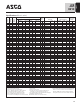
NORMALLY OPEN (Open when de-energized), NBR Seating (PA Disc-Holder, except as noted)
3/8 16 2.6 0.0 10 10 9 9 9 6 82 65 8210G033 23D
l
- - - 10.1/F 11.6/F
3/8 16 2.6 0.3 17 14 14 17 14 14 82 82
8210G011 « »
39D
l
- - - 10.1/F 11.6/F
1/2 16 3.4 0 10 10 9 9 9 6 82 65
8210G034 3
23D
l
- - - 10.1/F 11.6/F
1/2 16 2.6 0 10 10 7 9 9 6 82 65 - - -
8210G030 3
37D
l
10.1/F 11.6/F
1/2 16 3.4 0.3 17 14 14 17 14 14 82 82
8210G012 « »
39D
l
- - - 10.1/F 11.6/F
3/4 19 4.7 0 10 10 9 9 9 6 82 65
8210G035 3
25D
l
- - - 10.1/F 11.6/F
3/4 16 2.6 0 10 10 7 9 9 6 82 65 - - -
8210G038 3
38D
l
10.1/F 11.6/F
3/4 19 5.6 0.3 - - - 17 14 14 - 82 8210C013 24D
l
- - - - 16.8/F
3/4 19 5.6 0.3 17 14 14 - - - 82 - 8210G013 46D
l
- -
l
16.1/F -
1 25 11 0 9 9 9 - - - 82 -
8210B057 ≈ …
34D
l
- - - 20/F -
1 25 11 0.3 - - - 9 9 9 - 82 8210D014 26D
l
- -
l
- 16.8/F
1 25 11 0.3 10 10 9 - - - 82 - 8210G014 47D
l
- - - 16.1/F -
1 1/4 29 13 0 9 9 9 - - - 82 -
8210B058 ≈ …
35D
l
- - - 20/F -
1 1/4 29 13 0.3 - - - 9 9 9 - 82 8210D018 28D
l
- - - - 16.8/F
1 1/4 29 13 0.3 10 10 9 - - - 82 - 8210G018 48D
l
- -
l
16.1/F -
1 1/2 32 19.5 0 9 9 9 - - - 82 -
8210B059 ≈ …
36D
l
- - - 20/F -
1 1/2 32 19.5 0.3 - - - 9 9 9 - 82 8210D032 29D
l
- -
l
- 16.8/F
1 1/2 32 19.5 0.3 10 10 9 - - - 82 - 8210G032 49D
l
8210G132 - - 16.1/F -
2 44 37 0.3 - - - 9 9 9 - 65 8210 103 30P
l
- -
l
- 16.8/F
2 44 37 0.3 9 9 9 - - - 82 - 8210G103 50P
l
8210G133 - - 16.1/F -
2 1/2 44 39 0.3 - - - 9 9 9 - 65 8210 104 27P
l
- - - - 16.8/F
2 1/2 44 39 0.3 9 9 9 - - - 82 - 8210G104 51P
l
- -
l
16.1/F -
Specifications (Metric units)
¿ 0.3 bar on Air; 0.0 bar on Water.
¡ Valve provided with PTFE main disc.
¬ Valve includes UItem (G.E. trademark) piston.
√
Letter “D” = diaphragm construction; “P”= piston construction.
ƒ m Safety Shutoff Valve; l General Purpose Valve.
Refer to Engineering Section (Approvals) for details.
≈ Valves not available with Explosionproof enclosures.
∆
On 50 hertz service, the watt rating for the 6.1/F solenoid is 8.1 watts.
« AC construction also has PA seating.
» No disc-holder.
… Stainless steel disc-holder.
= UL listed for fire protection systems per UL429A 120/60,
110/5024VDC, no prefix and voltage options offered.
‡
DC constructions must have solenoid mounted vertical and upright.
3 ATEX/IECEx certified with prefix “EV”.
t ATEX/IECEx certified for DC only with prefix “EV”.
u Not available in 6 Volt DC. EF and HB prefix only.
S Valve available with lead-free brass body and bonnet using
suffix “LF”. The term “Lead-Free” for brass materials is
defined by SDWA 1417 as having a maximum weighted
average lead content of 0.25% on the wetted surface area.