
Instruction Manual


Cartridge Heaters
I 3
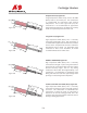
Ins
ert
ion
Len
gth
Lea
d
Len
gth
X
X
X
Y
Y1
Thr
ead
Len
gth
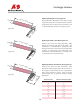
Ins
ert
ion
Len
gth
Lea
d
Len
gth
Thread
Len
gth
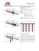
Ins
ert
ion
Len
gth
Lea
d
Len
gth
Hol
e s
ize
& l
oca
tio
n
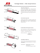
Dia
met
er
Dia
met
er
Dia
met
er
Thi
ckne
ss
Diameter
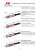
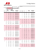
Figure 260
Figure 261
Figure 262
S
ingle and Double Threaded Fittings,
Figures 260 & 261
Single or double threaded fittings attached to sheath
to allow for installation into threaded holes.
Fitting - Brass, Steel and Stainless Steel
Materials
Leadwires
- Fiberglass for high temperature
applications
- Teflon for moisture protection
- Stainless Braid or Hose for flexing
applic
ations and abrasion protection
Terminal - General purpose and moisture resistant
Boxes housings
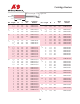
Heater NPT Size X Dimension Y Dimension Y1 Dimension
Diameter
1
/
4
”
1
/
8
-27
3
/
8
”
3
/
16
”
1
/
4
”
3
/
8
”
1
/
4
-18
1
/
2
”
3
/
16
”
1
/
4
”
1
/
2
”
3
/
8
-18
9
/
16
”
1
/
4
”
1
/
4
”
5
/
8
”
1
/
2
-14
5
/
8
”
1
/
4
”
5
/
16
”
3
/
4
”
3
/
4
-14
3
/
4
”
1
/
4
”
3
/
8
”
7
/
8
” 1-11
1
/
2
3
/
4
”
1
/
4
”
3
/
8
”
1” 1-11
1
/
2
3
/
4
”
1
/
4
”
3
/
8
”
1
1
/
4
” 1
1
/
4
–11
1
/
2
7
/
8
”
5
/
16
”
1
/
2
”
Mounting Flanges, Figure 262
Mounting flanges are recommended for applications
where vibration or movement may cause the heater to
be dislo
ged from its hole. Stainless steel flanges are
available in a variety of sizes and configurations. The
standard flange is round and is supplied with two
mounting holes
. For heaters 5/8" diameter and under,
the flange would be 1 1/2" in diameter. For larger
diamet
er hea
ters the standard flange would be 2.00" in
diamet
er.