Digital Video Recorder User’s User s Manual HD-SDI 4CH 1
Thank you for using our product. 1. This is user's manual for H.264 HD DVR (Digital Video Recorder). 2. This manual contains product specification and introduction, installation guide, operating guide and other necessary matters for easy understanding. Users should read this user's manual carefully for proper use. 3. Contents in this manual may be changed according to the specification change and f t feature improvement i t without ith t any notification. tifi ti 4.
CONTENTS Contents CH 1. Product Introduction 1-1. Product Contents 1-2. Specifications 1-3. Product Characteristics 1-4. Name of Each Part 5 6 7 9 CH 2. Installation Guide and Cautions 2-1. Cautions 2-2. Product Installation 2-2-1. Power Connection 2 2 2 Connecting External Device 2-2-2. 11 14 14 14 CH 3. How to Use 3-1. General Usage Information 20 3-2. Live Mode 3 2 1 Live 3-2-1. Li mode d control t l 3-2-2. Live mode feature 21 21 23 3-3. Search Mode 3-3-1. Search selection type 3-3-2.
CONTENTS Contents Trouble Shooting 48 Warranty 49 Appendix pp A How to Connect Receiver (ULTIMA-X Only) 50 Appendix B Catcheye for Android mobile 52 Appendix C Catcheye for iPhone 58 4
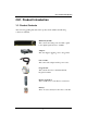
CH 1 Product Introduction CH1. Product Introduction 1-1. Product Contents After removing packing materials of this product, check whether all following contents are included. Main Body (DVR): This converts the analog video and audio signal to the digital signal and saves on HDD. Adapter: p supplies pp ppower to the pproduct. This 12V adapter Power Cable: This connect the adapter and the power source. g CD: Program This contains the User’s manual and Client Program for DVR.
CH 1 Product Introduction 1-2. Specifications Video Input : 720p, 1080i, 1080p Recording Speed : 720p :1~120fps 1080p : 1~120fps Compression Method : H.264 Technology Power : DC12V, 4.
CH 1 Product Introduction 1-3. Product Characteristics 1)) HD Video This DVR can record HD and Full HD video with extreme quality. Also it displays real HD(1920X1080) resolution, and therefore it provides the most clear image quality and the best security level. 2) High reliability With Embedded hardware and software design, this maintains higher product reliability.
CH 1 Product Introduction 11) Display information in easy-to-understand information method Thi enhanced This h d convenience i off user bby di displaying l i iinformation f ti (date, (d t time, ti recording di method, recording frame number, HDD capacity and others) in monitoring, recording and playing mode in easy-to-understand way. 12) P/T/Z control By built in RS485, various P/T/Z cameras can be used.
CH 1 Product Introduction 1-4. Name of Each Part [Front Panel] 3. STATUS RAMPS 1. IR WINDOW 2. USB 1. IR Window : the window for remote controller 2. USB ports : These USB ports are for mouse and USB devices. You should connect correctly the USB devices and mouse as picture directed directed. 3. Status lamps POWER : Blue color back light. Power indicator. RECORD : Red. Indicate the recording. NETWORK : Green.
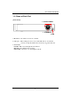
CH 1 Product Introduction [Rear Panel] 9.SENSOR IN 10. AUDIO IN 11.AUDIO 8.RELAY OUT 7.RS485 13.Xbox Extender (option) 1.FAN 3. LAN 12.HDMI 4.SPOT 5. VGA 6. POWER 2.VIDEO IN 1. Cooling Fan 2. Video In: This receives images from SDI cameras. 3. LAN Port: This is the Gigabit Ethernet LAN cable connection terminal. 4. SPOT Out : To CRT 4:3 monitor for spot video. 5. VGA port: video output for analog RGB display 6. DC Power : DC12V 4.0A or up 7. RS485 port : For control the pan and tile cameras.
CH 2 Installation Method and Cautions CH2. Installation Method and Cautions 2-1. Cautions WARNING Risk of electric shock. Do not open the cover of the product. Servicing of this product by unauthorized personnel is prohibited and will result in a void of warranty. In order to ensure the most stable conditions for power, the use of a UPS (Uninterrupted Power Supply) is recommended. - Avoid installing the product where there are direct rays or it is hot by locating near from heat generator.
CH 2 Installation Method and Cautions - Keep the power cord untwisted. (May cause fire or electric shock.) - Use proper adapter. (Using too much electric power may cause fire or electric shock.) - Do not install it at where exposed to rain and wind and water drop. (May cause fire, electric shock and transformation.) - Keep away from fire. (May cause fire.) -Do not disassemble or remodel on your own. (May cause malfunction or electric shock.) - Do not put next to flammable materials like flammable spray.
CH 2 Installation Method and Cautions Note : This equipment has been tested and found to comply with the limits for a Class A digital device device, pursuant to part 15 of the FCC Rules. Rules These limits are designed to provide reasonable protection against harmful interference when the equipment is operated in a commercial environment.
CH 2 Installation Method and Cautions 2-2 Product Installation Thi product This d t may bbe composed d off camera and d monitor it iin default, d f lt andd additionally dditi ll the sensor, microphone, speaker and PC for network can be connected if necessary. 2-2-1. Power Connection 1) Connect adapter cable to power connection terminal at rear side. 2) Input AC power to the adapter. (free voltage from 100V to 240V, 50/60Hz) ※ You must operate it at the rated voltage instructed on the user's manual.
CH 2 Installation Method and Cautions 2) How to connect external sensor Sensor terminal is composed of 1 input channel and 1 output channel. Sensor out terminal is relay output with 1A, 1A 24V or 0.5A,125V. 0 5A 125V SIREN SENSOR - + POWER Sensor In : Connect the sensors. The sensor are composed of both signal and ground terminals, with a voltage difference of 5V.
CH 2 Installation Method and Cautions 4) Connection Using PTZ camera In case of using pan and tilt cameras, connect PAN/TILT DRIVE to product as shown h att following f ll i figure. fi VIDEO CABLE SPEED DOME RS485 CABLE 5) Installing Hard disk drive In case of installing the hard disk drive, drive open the upper case and install the hard disk drive on the hard bracket. Remember that the main power should be off to install the hard disk drive.
CH 3 How to Use CH3. How to Use 3-1. General Usage Information The ULTIMA series DVR can be operated with a mouse or remote controller under the four main modes listed below: Live Mode – This is the “main or default” mode. From this mode you can view in real time all currently operating cameras, information regarding camera status, and have access to Pan/Tilt camera controls.
CH 3 How to Use 3-2. LIVE Mode IIn this hi section i you will ill know k how h to split li the h video id mode d into i 1, 1 4, 4 6, 6 8, 8 9, 9 12, 12 16, 16 as well as auto sequencing, PTZ Control, Mouse control, Setup configurations, Backup 3-2-1. LIVE Mode Control 1) Live View Status You may use the Live Menu Bar located at the bottom for quick shortcuts and view status of certain items.
CH 3 How to Use Date Time Screen Split mode change Sequence activation Hard drive usage Lock/ Unlock indicator Scheduler activation indicator Audio out channel indicator Mute indicator 3) Live Popup Menu By Right-Clicking anywhere on Live Screen, you may view the Live Popup Menu. By using the Live Popup Menu, you can quickly jump to the necessary configuration and settings.
CH 3 How to Use 3-2-2. LIVE Mode Feature 1) Split Change video split mode for Live View. 20ch : 1/6/12/20 Split Mode 2) Audio Out You can choose the audio out from this menu. 3) Instant Replay This is very convenient function to catch the abrupt accident. During live viewing, you can go directly to the playback screen. If you choose the ‘Instant Replay’ , the DVR goes to the ‘PLAY’ with the present time screen. And you can use the functions related playback.
CH 3 How to Use 4) Backup Th are two There t ways to t enter t the th backup. b k The Th first fi t one is i that th t right i ht click li k on the th live li screen, and the second one is that enter directly from ‘Search’ upon playback. If you choose the ‘backup’ from the live menu, below backup screen appears. • You can set the backup device, time and channel from the backup screen. • After that, if you push the ‘Estimation’ button, it will show the estimated backup file size.
CH 3 How to Use 5) PTZ (Pan, Tilt and Zoom) It is i possible ibl tto control t l the th pan andd tilt camera by b itself. it lf Press P the th ‘PTZ’ button b tt to t enter the PTZ mode. For Menu setting, you can set it by pressing button as displayed at bottom of window. • You can set the direction of camera by using the arrow buttons. • Setup : If you press Setup using mouse (or Menu button on the remote controller) in PTZ Menu, PTZ setup window will appear.
CH 3 How to Use •Preset : You can enter the preset number using the keypad appearing the preset button or ‘Enter’ button on the remote controller. 6) Zoom Digital zoom of live screen for selected channel. It can be 2x zoom and also control the position by mouse dragging.
CH 3 How to Use 7) Sequence Sequence Mode On /Off: Switches screens as set on Dwell time under Screen Setup 8) OSD This feature shows current settings of product through GUI (Graphic User Interface) and INFO button at front side is used for this feature. When you turn on power, this will show current date and time, System Lock Setting, HDD usage, Video Loss Check, Sensor ON/OFF, Motion Detection Check, Recording Stat us and Schedule Feature Usage.
CH 3 How to Use 3-3. Search Mode Search mode consists of two different modes of searching. The video data can be selected by Time or Event. Search Month / Day / Time selection. Select from Event Log 3-3-1.
CH 3 How to Use 2) Event Based Search Selection - Select search date from calendar - Event log will be displayed according to the chosen date - Preview pane above the Event Log will show preview of currently selected video - You may click on Refresh, Option, Backup, Import, To Live, To Play for additional features and options 3) Miscellaneous Search Options R l d all Reload ll data d t list. li t Search option. Backup recorded data to external USB device.
CH 3 How to Use 3-3-2. Play Mode If you choose ‘to play’, the full screen appear. You can control the play speed in here. ▶ Play Screen GUI 1. Split Screen 2. Sequence q 3. FB (Fast Backward): FB×2, 4, 8, 16, 32, 64 times faster 4. Playback : Backward normal speed 5. SB (Slow Bacward):SBx1/2, SBx1/4 6. STILL (Pause) / Frame advance 7. SF (Slow Forward):SFx1/2, SFx1/4 8. Play : Forward normal speed 9. FF (Fast Forward): FF×2, 4, 8, 16, 32, 64 times faster 10.
CH 3 How to Use 3-4. SETUP Mode Access S A Setup t menu ffrom Ri Right ht Cli Clicking ki mouse button b tt to t Popup P Menu. M Configure Display, Record, Device, Network, System which is navigated by clicking on corresponding tab menu at the top of the screen 3-4-1. Display Configure OSD, Main Display, Color Control setting.
CH 3 How to Use 2) Display Configure and view Monitor, Sequence Dwell Time settings. Monitor : You can choose the monitor between VGA and composite. The screen size will be optimized with the selected monitor. Full Screen 4:3 ratio: Set the full screen ratio from 16:9 to 4:3 for getting original picture. 3) SPOT Control Set the SPOT output . You can set the SPOT output. ode : C Choose oose ‘Full’ u oor ‘Quad’. Quad . - Mode - Sequence dwell time: Adjust the switching time.
CH 3 How to Use 3) Color Control Adjust color control for Video. You can adjust images of camera by channels. - Contrast: Adjust contrast of camera. - Brightness: Adjust brightness of camera. - Saturation: Adjust saturation of camera. - Hue: Adjust color of camera.
CH 3 How to Use 3-4-2. Record Configure and view Event In, Record, Group, Holiday settings 1) Record With this menu, you can set the recording variables of DVR and the Scheduler. 1) Rec type: to set conti, event, C/E(conti and event) and none(not recording). 2) Audio Rec: to select audio recording or not. 3) Conti Recording: continuous recording mode setting. ① Resolution: This is the D1 real time machine. Therefore the resolution fixed to D1( 704X480 in NTSC OR 704X576 in PAL) PAL).
CH 3 How to Use ③ Quality: Set picture quality. As quality gets higher, screen quality gets better but saving period gets shorter because file size gets bigger. There are 4 steps t quality lit suchh as Super, S High, Hi h Medium M di andd Low L To save the setting, choose ‘Apply’ after setting. 4) Event Recording This is a window setting Event Record Mode. Setting method is same as Conti Recording method. Conti Recording and Event Recording can be operated simultaneously.
CH 3 How to Use 2) Group With this menu, you can set the group using the scheduler. If you choose ‘Group’ tab, you can see the similar screen with ‘Record’. The setting is similar. *In recording, Schedule recording setting is most preferred. So if you activate the weekly scheduler, you cannot record manually.
CH 3 How to Use 3) Holiday With this menu, you can add the holidays. Use the ‘Add’ button for adding the holiday and use the ‘Delete’ or ‘Delete All’ buttons for removing the existing holidays.
CH 3 How to Use 4) Event In With this menu, you can set sensor input, motion detection setup. You can also set each channel individually.
CH 3 How to Use 3-4-3. Device Configure and view Camera, Private Zone, Audio, Motion Detection, Alarm Out, PTZ settings and Controller. 1) Camera You may configure and/or view camera video type and general camera configuration. •Channel Name: You can set the camera name. •Disable : Disable current camera. It is useful when the signal is bad.
CH 3 How to Use 3) Audio •Audio Out: Select which channel will be heard during Live View. 4) Motion Detection Change settings for Motion Grid selection and Sensitivity Level. You can set multiple area. ① Sensitivity.: 3 steps ② All On/Off : This will activate or deactivate the motion detection of the all area.
CH 3 How to Use 5) Alarm Out There are 3 types trigger such as sensor input, motion detection and video loss. This setting is related that which trigger will be activate the action such as Relay, Popup, and Buzzer Alarm Out. Each type can have separate Duration value and also linked to selected camera. • Duration Time from 5 seconds to 60 seconds • Sensor Type: Selectable option is N.O. (Normally Open) / N.C.
CH 3 How to Use 6) PTZ Configure Pan/Tilt/Zoom camera for control via DVR System and Remote client Driver: Choose Driver to be suitable for PAN/TILT Camera manufacturer. You have to set Comport value according to the connected camera. There are more kinds of camera which can be supported. Please contact the tech support to want to know the other cameras cameras.
CH 3 How to Use 3-4-4. NETWORK C fi Configure andd view i Address, Add P Port, DDNS DDNS, E-mail, E il Control C l andd Status S settings i 1) Address Configure Network information for Remote client connection • DVR Name : Type the URL of DVR using virtual keyboard. • Type : It can be supported only Ethernet • DHCP (Dynamic Host Configuration Protocol) Set whether you want to use DHCP or not (On/Off) If you connect LAN after setting it to On, IP is allocated automatically.
CH 3 How to Use 3) DDNS This is the function to automatically change the IP of DVR to URL. This product supports the automatic DDNS service using manufacture’s internal server. Also you can choose Dyndns. 4) E-mail You can send the event with snapshot by email. Fill all the information correctly and push the ‘Email Test’. Also you can select each event individually by ‘Event Set’.
5) Control You can individually adjust the resolution and frame rates of video transmission within 600 frames based on CIF. ① Resolution : You can choose CIF or D1 ② FPS: FPS Y You can adjust dj t th the fframe rate. t ③ Quality: Set picture quality 6) Status This shows the information how many connections and what is the action of each connection connection. ① Connected IP : This displays all the connected IP. ② Watch User: This displays how many connection for live viewing.
CH 3 How to Use 3-4-5. SYSTEM Configure and view system Date/Time, User Authority, Storage, System Log and Configuration settings 1) Date/Time •Time Zone: Choose the time zone of your site. If you using the NTP function, it must be set correctly to your zone. •Daylight Saving Time: It enables to adapt the day light saving time automatically. • Date/Time: This sets product time. Input time by pressing number buttons after moving cursor with direction buttons. Be careful to move to backward.
CH 3 How to Use 3) Storage •Display the information and usage of the hard disk drives. If you press the ‘Format’ button on each HDD, only that HDD will be formatted. •Total : Display all the HDD usage being used for the product. If you press the ‘Enter’ button on here, all the hard disk drives will be formatted. • HDD Overwrite : Determine whether you want to continue recording if there is no p savingg space p at hard disk drives.
CH 3 How to Use 5) System Log You may view all System administration log from Setup Æ System Æ System Log. Also you can export the system log and easily send it to technical support for trouble shooting. 6) Configuration Shown at the following screen, from Setup Æ System Æ Firmware, you may view the current firmware version as well as Upgrade the firmware and additionally, Export, Import, and Default DVR Configuration.
CH 5 Client Program 3-5. Firmware Upgrade After installing Aft i t lli the th client li t software, ft you can find fi d the th ‘NetDownloader ‘N tD l d Program’ P ’ in i the th window programs (Start -> programs -> DVR Client -> NetDownLoader) . Please execute this ‘Net Downloader Program’ to upgrade the firmware of the DVR. After typing the IP and password of the DVR, click the ‘Connect’ button. You can check the model name and the current version.
CH 5 Client Program When you connect the DVR, click the ‘open’ button on the ‘NetDownloader Program ’and select the update file and then press the ‘start’ button. You can see the b l download below d l d window i d on the th DVR screen. ☞ WARNING!!! D not turn off Do ff the h power d during i d download l d procedure. d If you power off manually, all memory will be deleted ! ※ After upgrading, DVR will reboot automatically.
Trouble Shooting Trouble Shooting S Symptom C Checkpoint C Countermeasure ● Can't turn on power ● Is DVR connected to power supply cable? ● Connect power cable ● There is no image on monitor ● Are DVR and monitor turned on? ● Are cables of DVR connected?. ● Turn on power. ● Connect DVR cable. ● Only INFO OSD is on monitor and no image ● There is Video Loss message.
Warranty Warranty This product guarantees free repair based on guarantee regulations only if the malfunction is caused while customers were using it properly. Warranty Period Warranty period begins from the day this product is delivered to customer. Model Name Warranty Period From . . . To . . . (for year) Address : User Company : NAME : TEL : Address : Retailer Company : NAME : TEL : In case the malfunction is caused by one of following reasons, repair shall be provided as charged service.
Appendix A Appendix A How to Connect Receiver (ULTIMA X O (ULTIMA-X Only) l ) 1. Connect EXTEND FTP cable to Receiver (upto 350ft/100m). Refer to http://en.wikipedia.org/wiki/Twisted_pair about the FTP cable. Connect Monitor and Wired/Wireless Mouse to the Receiver FTP(Foiled Twisted Cable) Receiver 2. Because all the case has different cable length, you should adjust the GAIN and PHASE in Receiver to get a most proper VGA output.
Appendix A 3.This is the whole diagram.
Appendix B Appendix B Catcheye for Android mobile The Catch Eye allows for you to monitor DVRs. It now supports Live mode. Playback mode will be added soon. It is easy and convenient to use. The functions of Catch Eye: • Live View • 1/4/16 division • Channel switching • Server management • PTZ control • Digital zooming • Snapshot The functions operated by Touch: • Single touch : switch channel, Pan/Tilt. • Multi touch : Digital-Zoom, PTZ Zoom-In/Out 1.
Appendix B 2. Server Management Enter the appropriate data of your DVR server. - Server Name : Name that you want to associate with the DVR server. - IP address : IP address(example : 192.168.1.110) or a DNS name(example : 12345.3r.global.com). - Server Port : Port number(watch port in DVR setup). - User Name : Username(default is "admin"). - Password : User password. - Server Type : Embedded DVR, HD DVR, PC DVR When you finish, tap the "Save" button.
Appendix B The "Edit“ button modifies the information of the selected DVR Server. 3. Live Viewing Tap the DVR server item and select the “Connect” in menu when you register DVR server. The app. will show “loading, Please wait” as below. ** Wait Until it receives DVR channel data, it will take a few seconds depending on the network environment. 3G will take a longer time than WiFi.
Appendix B The next screen shows the first channel on DVR live view. “Channel", “Division“, “Save“, “PTZ” or “Zoom“ buttons are shown in menu. 4. Multi Channel Viewing - "Channel“, “Division” button If you select these buttons, sliding view will appear in live view so that you can change the channel or division that you want. Max channel depends on server’s se ve s max channel, c e , andd division d v s o type ype iss 1,4 , andd 166 division d v s o mode.(16 ode.
Appendix B 5. Image Saving - "Save" button "S " bbutton captures current iimage. If you capture an iimage bby tapping "Save" i "Save" button, you can find the image file in your phone’s Gallery menu. 6. PTZ Control Mode - "PTZ" button The "PTZ" button allows you to control PTZ camera If the camera type of the channel is PTZ, the fourth button on the bottom bar will be named "PTZ". "PTZ" Otherwise, Otherwise “Zoom“. “Zoom“ Every PTZ function is controlled by touch.
Appendix B - Zoom-In/Out The Zoom-in/out function is controlled by multi touch from inside to outside or from outside to inside. The app. will show “+” icon in Zoom-in mode or a“-” icon in Zoom-Out mode on the screen as below. 7. Digital-Zoom Mode If the camera type is not pan-tilt, you can control the Digital zoom function. supported functions are as below. - Digital Zoom-in - Digital Zoom-out Every Digital Zoom function is controlled by your touch.
Appendix C Appendix C Catcheye for iPhone The Catch Eye allows for you to monitor DVRs. It now supports Live mode. Playback mode will be added soon. It is easy and convenient to use. The functions of Catch Eye: • Live View • 1/4/16 division • Channel switching • Server management • PTZ control • Digital zooming • Snapshot The functions operated by Touch: • Single touch : switch channel, Pan/Tilt. • Multi touch : Digital-Zoom, PTZ Zoom-In/Out 1.
Appendix C 2. Server Management Enter the appropriate data of your DVR server. - Title : Name that you want to associate with the DVR server. - IP address : IP address(example : 192.168.1.110) or a DNS name(example : 12345.3r.global.com). - Port : Port number(watch port in DVR setup). - Username : Username(default is "admin"). - Password : User password. - Server Type : Embedded DVR, HD DVR, PC DVR When you finish, tap the "Save" button.
Appendix C The "Edit“ button modifies the information of the selected DVR Server. 3. Live Viewing Go ahead and tap the DVR server item in Addressbook table when you register DVR server. The app. will show “loading circle icon” as below. ** Until it received DVR channel data, it takes a few seconds(it depends on network environment.
Appendix C The next screen shows DVR live view for first channel. "CH", "Save" and “Digital-Zoom" or "PTZ“ buttons are shown in the bottom bar. 4. Multi Channel Viewing - "CH" button If you tap this button, sliding view will appear in live view and you can change channel and division mode. Max channel depends on server’s max channel, h l andd division di i i type is i 1 channel, h l 4 channel h l andd 16 channel h l mode. d Iff you finish change channel or division, tap "CH" button in bottom bar again.
Appendix C 5. Image Saving - "Save" button "S " bbutton capture 1 channel "Save" h l iimage. If you capture iimage by b tapping i "Save" button, you can find image file in iPhone's photo album menu. 6. PTZ Control Mode - "PTZ" button "PTZ" button makes you can control PTZ camera If camera type off the h channel h l is i PTZ, PTZ the h third hi d button b in i the h bottom b bar b will ill be b named "PTZ". Otherwise, “Zoom“. Every PTZ functions are controlled by your touch.
Appendix C - Zoom-In/Out Zoom-in/out function is controlled by multi touch from inside to outside or from outside to inside. The app. will show “+” icon in Zoom-in or “-” icon in Zoom-Out in the screen as below. 7 Di 7. Digital-Zoom i lZ Mode M d If camera type is not pan-tilt, you can control digital zoom function. supported functions are like below. - Digital Zoom-in - Digital Zoom-out Every Digital Zoom function is controlled by your touch.
Appendix D 8. DVR Information If you tap the "i“ button in top bar, you can see the DVR server’s information.