
Installation guide

Page 12
NetStacker NMM Lite Installation Guide
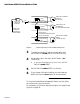
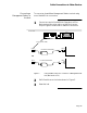
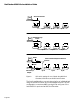
DIP Switch 2 is used when the hub is connected to an
out-of-band management station, a modem, or a local terminal
using the RS232 connector.
See Figure 9 on page 20 and Figure 10 on page 21 for a sum-
mary of the DIP switch settings.
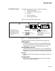
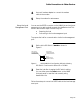
The label on the NetStacker chassis back panel provides a basic
explanation of the LEDs and DIP switches.
Interpreting the Back
Panel LEDs
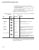
Table 1 describes the six LEDs on the back panel of the NMM Lite.
Table 1 NMM Lite LEDs
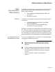
Use the
Reset
push-button to manually reset all modules and soft-
ware on the NetStacker hub. Power on diagnostics run automati-
cally when the hub is reset.
LED
Display
Position
Color/State Meaning
CPU Active Green, Blinking Blinking LED indicates CPU is operating normally.
SNMP Traffic
Link/Receive
Green, Blinking Blinking LED indicates SNMP packets being
transmitted to module.
Collision Yellow, On Indicates a collision has occurred.
Misaligned,
CRC error
Yellow, On MC - Misaligned/CRC. Received data frame not
integer multiple of eight bits (or one byte) and/or
CRC error.
OOB Traffic
Out-Of-Band
Green, On
Green, Blinking
Indicates out-of-band traffic to/from NetStacker
hub. Note: Functions only when NMM Lite is in
operational mode.
Blinking LED indicates receiving in out-of-band.
RS232 Setup Mode Yellow, On
Green, Blinking
Indicates Setup switch is in “Down” position
(setup mode) during power up cycle.
Blinking LED indicates AsantéView Management
Station (AMS) is communicating with RS232 port
or out-of-band is transmitting.