NetStacker NMM Lite Installation Guide • Introducing the NMM Lite on page 5 • Installing the NMM Lite on page 8 • The Back Panel on page 11 • Cable Connections to Other Devices on page 13 • Using AsantéTerm on page 22 • Using Telnet on page 24 • Using the Asanté Remote Management System on page 27 • Configuration Menu on page 34 • Technical Specifications on page 40 • RS232 Connections on page 41
NetStacker NMM Lite Installation Guide Copyright Notice Copyright 1994 by Asanté Technologies, Inc. All rights reserved. No part of this manual, or any associated artwork, software, product design or design concept, may be copied, reproduced or stored, in whole or in part, in any form or by any means mechanical, electronic, optical, photocopying, recording or otherwise, including translation to another language or format, without the express written consent of Asanté Technologies, Inc.
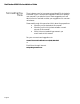
Asking for Assistance Asking for Assistance Asanté Technical Support To contact Asanté Technical Support: Telephone (800) 622-7464 (408) 435-0706 Fax (408) 432-6018 Fax-Back1 (800) 741-8607 (408) 954-8607 Bulletin Board Service (BBS)2 (408) 432-1416 ARA BBS (guest log-in)2 (408) 894-0765 AppleLink mail3/BBS2 ASANTE.TECH FTP Archive2 ftp.asante.com Internet mail3 support@asante.com 1. 2. 3. Technical Support Hours Please request catalog of contents. Download INDEX.
NetStacker NMM Lite Installation Guide Tell Us What You Think There’s always room for improvement and Asanté Technologies is interested in your comments and suggestions about our product user manuals. If you take the time to make suggestions, we will take the time to read and consider your suggestions for new manual releases.
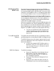
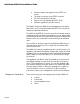
Introducing the NMM Lite Introducing the NMM Lite The Asanté Network Management Module Lite (NS-NMM), or NMM Lite, is a daughter board specially designed to be mounted on the double-height RJ45B or RJ21B module. Its function, as the intelligence of the NetStacker hub, is to manage and gather statistics on a single NetStacker hub or on a stack of NetStacker hubs.
NetStacker NMM Lite Installation Guide ❏ ❏ ❏ ❏ ❏ Remote network management via an RS232 connector Terminal connection via an RS232 connector Six LEDs as hub alert visual aids Support for Hub Repeater MIB (RFC 1516) Software upgrade using Flash memory The NMM Lite supports SNMP and the Management Information Base (MIB) I and II, the Hub Repeater MIB (RFC 1516), as well as Asanté’s private MIB extensions. The AMS Link and RS232 connectors provide out-of-band network management.
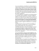
Introducing the NMM Lite You can use AsantéView or AsantéView Lite In-Band software for in-band network management. In-band management lets network managers manage, control, and monitor their networks via SNMP protocols over the Ethernet communications channel of an Ethernet network. In-band refers to the fact that the network management packets travel over the same network that all other network information travels.
NetStacker NMM Lite Installation Guide Installing the NMM Lite To install the NMM Lite daughter board, you perform the following operations: ❏ ❏ ❏ ∆ Checking Package Contents ❏ ❏ Mounting the NMM Lite Daughter Board The Asanté NMM Lite in anti-static packaging This installation guide The warranty card Before you handle the RJ45B or RJ21B mother board and the NMM Lite daughter board, you must attach the grounding strap (provided in the package) to your wrist to discharge static electricity from your
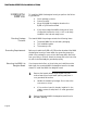
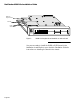
Installing the NMM Lite ∆ Handle the board by its edges. Do not touch the connectors or chips. 3 Screw in the thirteen standoffs, provided with the NMM Lite daughter board, into the holes in the mother board. 4 Position the NMM Lite (printed circuit side facing up) over the mother board, placing its holes over the standoffs on the mother board. Push down gently to seat the board. Figure 1 shows a top view of the NMM Lite daughter board mounted on the mother board.
NetStacker NMM Lite Installation Guide NMM Lite daughter board standoffs RJ21B mother board 1 UPLINK 0 AUI PARTITION 2 3 4 5 6 7 8 9 10 11 12 SEG1 1 2 3 4 5 6 7 8 9 10 11 12 SEG 0 1 UPLINK 0 AUI PARTITION NetStacker Base Hub Figure 2 2 3 4 5 6 7 8 9 10 11 12 SEG1 1 2 3 4 5 6 7 8 9 10 11 12 SEG 0 NetStacker-RJ21 LINK/RECEIVE NMM Lite daughter board installed on mother board You are now ready to install the RJ45B or RJ21B board in the NetStacker chas
The Back Panel The Back Panel The NMM Lite back panel, shown in Figure 3, includes: ❏ One RS232 connector Two AMS Link RJ45 connectors Six LEDS Two DIP switches One Reset push-button ❏ ❏ ❏ ❏ Figure 3 shows the NMM Lite back panel. RS-232 RJ45 (AMS LINK) THIS EQUIPMENT COMPLIES WITH THE REQUIREMENTS IN PART 15 OF FCC RULES FOR A CLASS A COMPUTING DEVICE.
NetStacker NMM Lite Installation Guide DIP Switch 2 is used when the hub is connected to an out-of-band management station, a modem, or a local terminal using the RS232 connector. See Figure 9 on page 20 and Figure 10 on page 21 for a summary of the DIP switch settings. The label on the NetStacker chassis back panel provides a basic explanation of the LEDs and DIP switches. Interpreting the Back Panel LEDs LED Display Position Table 1 describes the six LEDs on the back panel of the NMM Lite.
Cable Connections to Other Devices Cable Connections to Other Devices The NMM Lite’s back panel has two types of connections (out-ofband) that let you attach other hardware devices such as PCs, Macs, or dial-up modems: ❏ ❏ AMS Link Two AsantéView Management System (AMS) Link connectors One RS232 connector The AMS Link specifically provides the following types of device connections: ❏ ❏ PC and Macintosh connections for Out-of-Band network management Hub interconnections for out-of-band (daisychained fr
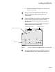
NetStacker NMM Lite Installation Guide Mac or PC AMS Link Extender DIP Switch 2 DOWN (SETUP) on all hubs RJ45 Hub/Hub Stack 1 1 2 DIP Switch 1 UP (THROUGH) on all intermediate hubs to Mac or PC AsantéView Management Station (AMS) Hub/Hub Stack 2 1 2 (up to 9 more intermediate hubs/hub stacks can be connected) End Hub/Hub Stack Figure 4 DIP Switch 1 DOWN (END) on end hub only 1 2 Connecting hubs in an Out-of-Band daisy-chain 3 To enable termination in the out-of-band daisy-chain, set DIP Swi
Cable Connections to Other Devices Connecting a Management Station to the Hub To connect an AsantéView Management Station to a hub using one of the AMS Link connectors: 1 Connect one end of the AMS Link Extender to a PC or Macintosh and the other end to an AMS Link connector port. Figure 5 shows how to make this connection.
NetStacker NMM Lite Installation Guide RS232 Connector You can use the RS232 connector on the NMM Lite back panel to connect the NetStacker Hub to: ❏ ❏ ❏ An AsantéView Out-of-Band Management Station A modem A local terminal Using out-of-band management, you can gather statistics and set parameters for up to twelve stacks of Asanté NetStacker Hubs or any combination of twelve daisy-chained hubs. See Figure 3 on page 11 for an illustration of the RS232 connector on the NMM Lite back panel.
Cable Connections to Other Devices Using the Local Management Port 4 Use a null modem adapter to connect the modem cable to the modem. 5 Set up the modem for auto-answer. You can use the RS232 connector on the NMM Lite as a local management port to gain terminal access to the NetStacker hub.This section describes the steps involved.
NetStacker NMM Lite Installation Guide 1 Be sure the distance from the management station to the hub is less than 50 feet. 2 Connect a straight-through RS232 cable (included with AsantéView software) to the RS232 connector on the NMM Lite. Figure 7 shows a Macintosh RS232 cable being connected to the NMM Lite RS232 connector. RS-232 RJ45 (AMS LINK) THIS EQUIPMENT COMPLIES WITH THE REQUIREMENTS IN PART 15 OF FCC RULES FOR A CLASS A COMPUTING DEVICE.
Cable Connections to Other Devices With a PC, you can use Windows Terminal (included with Windows software) or another terminal emulation program. Refer to the documentation that comes with Windows for more information. Use the following parameters to connect to the hub: ❏ ❏ ❏ ❏ Summary of DIP Switch Settings 9600 baud 8 data bits N (no parity) 1 stop bit Figure 9 on page 20 and Figure 10 on page 21 show the required DIP switch settings for the NMM Lite in five configurations.
NetStacker NMM Lite Installation Guide AMS AMS AMS Link Extender 1 2 1 2 1 2 1 2 Hub Hub Hub Hub RJ-45 AMS RJ-45 Straight-through RS232 1 2 1 2 1 2 1 2 Hub Hub Hub Hub RJ-45 AMS RJ-45 RS232 RJ-45 RJ-45 Public Switched Telephone Network (PSTN) modem RS232 1 2 Hub Null modem adapter Figure 9 modem RJ-45 1 2 1 2 1 2 Hub Hub Hub RJ-45 RJ-45 DIP switch settings for out-of-band using AMS Link Extender, RS232 direct, and RS232 with modem The fourth configuration connect
Cable Connections to Other Devices Straight-through RS232 Terminal only this device is managed Configuration 4 Local management port 1 2 1 2 1 2 1 2 Hub Hub Hub Hub Ethernet backbone AMS AMS AMS Link Extender Configuration 5 Out-of-Band single hub 1 2 Hub Figure 10 DIP switch settings for Local Management Port, and AMS Link Extender with single hub Page 21
NetStacker NMM Lite Installation Guide Using AsantéTerm AsantéTerm, provided with AsantéView and AsantéView Lite In-Band and Out-of-Band, can be used to interrogate and program a NetStacker hub using a Macintosh computer as a terminal. Before using AsantéTerm, you need to configure the NMM Lite as a local management port to gain terminal access to the NetStacker hub. See "Using the Local Management Port" on page 17 for instructions.
Using AsantéTerm Figure 12 shows the first Asanté Management System screen that appears for the NetStacker NMM Lite. Figure 12 3 Asanté Local Management System Main Menu using AsantéTerm Type g to see the current configuration.Type c to configure the NMM Lite.Type s for a submenu that helps you select hub statistic parameters.
NetStacker NMM Lite Installation Guide Using Telnet You can use Telnet software (not included with the NMM Lite) to interrogate and program an NMM Lite module in a NetStacker hub.You can do this using any Telnet-capable computer, either directly connected to the hub or over the network. ∆ Information on installing Telnet is not provided in this manual. Refer to the documentation that comes with the Telnet software.
Using Telnet Copy the files to the AMS Images folder on the Macintosh. On the PC, copy the files to the same directory as the AMS executable (In-Band or Out-of-Band). Upgrading the Hub Image Code You can download the image code to the hub using AsantéView Lite (version 2.3 or later) In-Band or Out-of-Band, or AsantéView In-Band or Out-of-Band (version 2.3 or later).You do this by selecting the Software Upgrade command in the Configuration menu.
NetStacker NMM Lite Installation Guide Figure 14 4 Click the OK button. Figure 15 shows the Asanté Remote Management System Main menu that appears for configuring a NetStacker hub.
Using the Asanté Remote Management System Using the Asanté Remote Management System This section contains: ❏ ❏ ∆ General Guidelines General guidelines for using the Asanté Remote Management System menus A short tutorial for navigating the system menus The icons, menus, and screens for accessing the Asanté Remote Management System may differ depending on what computer you’re using. Once you’re in the Asanté Remote Management System, the menus look the same.
NetStacker NMM Lite Installation Guide Asanté Remote Management System Menu Tutorial The following short tutorial navigates through some of the Asanté Remote Management System menus.The tutorial adds the text “Rm 217” to a hub’s previously-defined name. All examples show Telnet running on a Macintosh. We start with a Telnet session established with a NetStacker hub. The Asanté Remote Management System Main menu appears, shown in Figure 16.
Using the Asanté Remote Management System Figure 17 General Configuration Screen Example The example shows “NetStacker-240” as the current hub name. If the hub has not had a name assigned to it previously, the Hub Name field will be blank. 2 Press the space bar to continue. The Asanté Remote Management System Main menu appears again (see Figure 16 on page 28). 3 Type c from the Asanté Remote Management System Main menu. The prompt “Enter Password” appears below the Command> line, shown in Figure 18.
NetStacker NMM Lite Installation Guide Figure 18 4 Type the password Asante (the password is case-sensitive) and press return. The Configuration menu appears, shown in Figure 19. Figure 19 5 Page 30 Enter Password Prompt Configuration Menu Type a from the Configuration menu.
Using the Asanté Remote Management System This takes you to the System Administration Information menu, shown in Figure 20. Figure 20 System Administration Information Menu Note that the current hub information—name, contact, and location—displays above the menu choices on this screen (some or all of these fields may be blank for your particular hub). We’ll change the example hub’s current name, “NetStacker-240”, to “NetStacker Rm 217” (you can type a different name if you wish).
NetStacker NMM Lite Installation Guide Figure 21 7 Page 32 Enter Hub Name Prompt Type NetStacker Rm 217 (or a different name if you wish) and press return. Note in the above example that even though it looks like we could just add the text “Rm 217” to the end of the hub name, we actually have to type the entire line. If we typed “Rm 217” only, the hub would be renamed “Rm 217” rather than “NetStacker Rm 217”.
Using the Asanté Remote Management System Figure 22 8 9 System Administration Information Menu Showing New Hub Name Press q to return to the Configuration menu. Press q again to return to the Asanté Remote Management System Main menu. You’ve just completed the tutorial for navigating menus in the Asanté Remote Management System. If you want to leave the Telnet application at this time, choose Quit from the File menu.
NetStacker NMM Lite Installation Guide Configuration Menu This section shows you how to access the Asanté Management System Configuration menu (Local or Remote) and then describes the menu choices you can use to configure your hub. All examples show Telnet running on a Macintosh. We start with a Telnet session established with a NetStacker hub. Accessing the Configuration Menu Use the following procedure to get to the Configuration menu.
Configuration Menu Configuration Menu Descriptions The following paragraphs describe the Configuration menu choices you can use to configure your NetStacker hub. System Administration Information Use to enter and transmit text strings defining the hub name, contact, and location. Out-of-Band Parameters Use to enter and transmit the Out-of-Band baud rate, dial string to be used when the AMS dials out on a modem, and the Out-of-Band password. Baud rate changes also will be effective on the terminal.
NetStacker NMM Lite Installation Guide Group Parameters Use to assign to a segment or isolate, meaning assign to no segment, a group. (A group is defined as all of the ports on a NetStacker hub module.) Pressing n (Select Next Group) repeatedly cycles through the group choices. Pressing s (Assign/Isolate Group Segment) repeatedly cycles through the segment choices—1 or Isolated for the NetStacker hub.
Configuration Menu ▲ If the aging time is set to too short a time span, problem nodes may time out and be dropped from the Node Summary table. You may have to experiment with the setting to find out what works best for your network. Console Password Use to set the password for the terminal interface connection. The password is case-sensitive, and it can be up to 20 characters.You’re prompted for this password when you choose the Configuration menu from the Asanté Remote Management System Main menu.
NetStacker NMM Lite Installation Guide Changing the Password You’re prompted for a password when you choose the Configuration menu from the Asanté Management System Main menu. (The default password is Asante.) You can change this password if you wish.The password is casesensitive, and it can be up to 20 characters. Use the following procedure to change the current password. All examples show Telnet running on a Macintosh. We start with a Telnet session established with a NetStacker hub.
Configuration Menu Figure 25 Enter New Password Prompt 4 Type the new password and press return. You’re prompted to type the new password again. 5 Type the new password a second time and press return. The new password is sent to the hub and you’re taken back to the Configuration menu. 6 Type q to exit the Configuration menu.
NetStacker NMM Lite Installation Guide Technical Specifications Physical Dimensions: 3” x 2”x 0.25” Weight: Approximately 0.5 lbs. (272.7g) Non-volatile Program Memory: Flash EPROM and EEPROM Environmental Conditions: Operating Temperature: 0° to 40° C ambient Operating Humidity: 5% to 90% noncondensing Operating Altitude: 10,000 ft. (3,048 m) maximum Storage Temperature: –30° to 80° C Storage Humidity: 5% to 90% noncondensing Storage Altitude: 25,000 ft.
RS232 Connections RS232 Connections Table 3 lists the pin assignments for a standard RS232 connector.
NetStacker NMM Lite Installation Guide Page 42
Asanté Technologies, Inc. 821 Fox Lane San Jose, CA 95131 December 1994 P/N 06-00145-01 Rev.