
Installation guide

Page 15
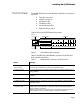
Pin-Outs and Cable Specifications
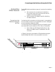
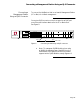
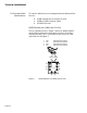
RJ45B to RJ45B Crossover Cable
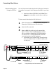
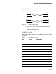
Figure 8 shows the RJ45B to RJ45B crossover cable.
Figure 10 RJ45B crossover cable
∆ Note: This manual assumes that straight-through
cabling is used for all configurations, except
where specifically noted.
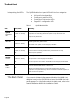
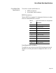
AUI (DB15) Pin-Outs
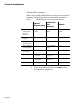
Table 3 lists the pin numbers, circuit and signal names for the AU
I
connector.
Table 4 AUI Connector Pin-Outs
Pin Circuit Signal Name
03 DO+ Data Out positive
10 DO- Data Out negative
11 DO S Data Out circuit Shield
05 DI+ Data In circuit positive
12 DI- Data In circuit negative
04 DI S Data In circuit Shield
07 CO+ Control Out positive (optional)
15 CO- Control Out negative (optional)
08 CO S Control Out Shield (optional)
02 CI+ Control In positive
09 CI- Control In negative
01 CI S Control In Shield
06 VC Voltage Common
13 VP Voltage Plus
14 VS Voltage Shield
Shell PG Protective Ground
3
6
1
2
3
6
1
2