
Installation guide

Page 8
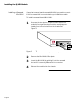
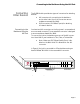
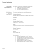
The Back Panel
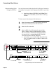
Interpreting the LEDs
The RJ45B Module front panel LEDs fall into four categories:
❏
AUI port link and partition
❏
Port-by-port partition LEDs
❏
Port-by-port link/receive LEDs
❏
Segment 1 configuration LED
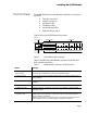
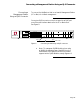
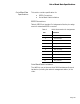
Table 2 RJ45B Module LEDs
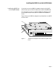
The Back Panel
If you mount a Network Management Module Lite (NMM Lite)
daughter board on the RJ45B mother board, the NMM Lite back
panel appears. For information about the back panel, refer to the
Asanté NetStacker NMM Lite Installation Guide
.
LED Color/State Meaning
AUI
Uplink
PARTITION
LED
Amber On, Blinking
Amber On, Steady
Off
Hub has autopartitioned uplink; high collision rate possible.
Operator has manually partitioned uplink or trap has been sent.
Uplink not partitioned.
AUI Uplink
LINK LED
Green On, Blinking
Green On, Steady
Blinking LED indicates hub is receiving traffic over uplink. Faster rate of
blinking indicates greater traffic.
No traffic over uplink, or link integrity is disable
PARTITION
24 LEDs
Amber On, Blinking
Amber On, Steady
Off
Autopartitioning.
Slot has been manually partitioned by administrator or trap.
Normal port operation.
LINK/
RECEIVE
24 LEDs
Green On, Blinking
Green On, Steady
Off
Blinking LED indicates hub is receiving traffic over port.
Link present or link integrity test disabled.
Link not present. Port status unavailable if link integrity test disabled.
SEG1 and
SEG2
2 LEDs
Green On, Steady
Off
With an NMM Lite, SEG1 is lit;
with an AH2072 NMM SEG1 or SEG2 is lit.
Board not seated properly or both LEDs intentionally set off by
operator. Though module may not be connected to network segment, it
still functions as repeater.