Voyager II Megapixel Pan/Tilt IP Camera User’s Manual Version 1.0 Content Content ........................................................................................................................... 1 Packaging Contents ........................................................................................................ 3 System requirements ...................................................................................................... 4 Introduction ......................................
Camera Setting from a Router ..................................................................................... 12 Change the Internet Explorer Setting ........................................................................... 13 Enter the Main Page ..................................................................................................... 14 Camera Main Page ....................................................................................................... 16 System setting ..............
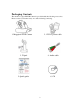
Packaging Contents The Asante Voyager-II PT IP Camera is provided with the following accessories. Please contact your dealer if any one of the following is missing. 1. Megapixel PT IP Camera 2. 12V DC power cable 3. Tripod 4. Audio cable 5. Quick guide 6.
System requirements ASANTE VOYAGER II PT IP Camera Internet Environment LAN 10/100M Ethernet Wireless LAN 802.11b or 802.11g Monitor System Requirements OS support Browser support Hardware Windows 2000 Professional SP4, XP Home SP2 Internet Explorer 6.x or later CPU: Pentium 4 2.
Introduction The Voyager II PT IP Camera is a multi-functional stand-alone PT Internet Camera that can connect to Ethernet, LAN, or any broad-band networks. Unlike traditional CCTV cameras, the Voyager II PT IP Camera has a built-in CPU and webpage server to provide users with a mechanism for home security or remote office monitoring applications. The Voyager II PT IP Camera supports 3GPP real-time video streams that allow you to control the home or office environment using a 3G mobile phone.
System Instructions 1. DC power cable: The DC input connector has a socket to connect the product to a power source. 2. Ethernet connector: A RJ-45 connector is provided for connection to the 10Base-T Ethernet cable or 100 Base-T High Speed Ethernet cable. This port can automatically detect or coordinate the transmission rate of the network. 3. Use a video/audio output cable for external video/audio transmission if required.
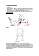
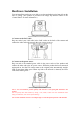
Note: The horizontal angle is important when you hang the product from the ceiling. Excessive inclination may bring about abnormal rotation of the camera lens. Fixed on a wall (Fig. 1) Fixed on a ceiling (Fig. 2) MIC in/Audio Out Plug the Audio cable to the back of the camera. The Red connector is for Microphone input. The Green connector is for Speaker out for connection to a sound amplifier or an amplified speaker. LAN Socket Insert your LAN cable in the LAN socket.
External alert bus (DI/DO) For more information about DI/DO, refer to Attachment A. Reset to factory settings After turning on the machine, press in this hole for 5 seconds using a sharp object to reset to factory settings. Built-in microphone The product is provided with built-in microphone pickup function. Don't block this hole if you want to use this function to acquire the best audio response. Link LED and Event LED 1.
Hardware Installation You can install the product on your desk or use the attached tripod to hang it from the wall or ceiling. (The product is provided with image flip function. Refer to the “Control Panel” for more information.) Confirm the position for installation of the camera 1. Connect to the LAN cable Plug one end of your LAN cable in the LAN socket on the back of the camera and connect the other end to the network that you want to access to. Pluck in LAN socket 2.
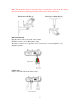
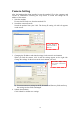
Camera Setting After the hardware has been installed, insert the attached CD in the computer and execute IP FINDER.EX following the steps below to search and change the IP address of the camera. 1. Start the machine. Execute the IP Finder.exe from the attached CD. 2. Search the camera (Search) Search the product from your LAN. The factory IP setting 192.168.0.20 appears on the screen. 1. Click Search to find the IPCAM on the LAN. 3.
3. Click Submit to validate new settings. 5. Confirmation When all changes have been confirmed, click Exit to quit. 4. When all changes have been confirmed, click Exit to quit. Notes: 1. The IP FINDER can only find the IP addresses of the cameras that share the same hub on the LAN. For information about finding IP addresses on the Internet, refer to the “DDNS Setting”, or “UpnP Setting”. 2. All Asante camera/network server products can be found and changed using the IP FINDER software. 3.
Camera Setting from a Router You can use DHCP when you want to use the camera on the Intranet (LAN). However, the IP must be set to fixed when you want to use the camera on a WAN. For this application, it is required to set up the function of the virtual server on the ADSL router. Follow the steps below to complete the setting: 1. Enter the camera setting page to set a fixed IP. (Refer to the “Network Setting”.) Ex.: 192.168.0.49 2. Enter the ADSL router main setting page. Ex.: Zonet ADSL router 3.
Change the Internet Explorer Setting The product uses ActiveX Control to play image and sound on your PC and the ActiveX Control application software will be downloaded to your PC when you connect it to the Internet. To ensure successful download of the software, the Internet Explorer "security settings" must be changed accordingly. Make sure that the security level is set to Level II, the commonly used default security level.
Enter the Main Page 1. Open the IE browser and key in the IP address of the product. Key in the IP address of the camera When the login screen appears, key in "root" in the User Name and Password fields. Click OK. Camera login screen 2. Key in the default “username” and “password”. User Name: root Password: root You can access the camera as an administrator by default and set up for other users or privileges from the “Basic Settings” -> “User”. 3.
Click “Install ActiveX Control”. Setup prompt screen 4. The security warning screen appears. Click "Install". The ActiveX Control is named "UIC ActiveX Control". This software is owned by UIC and well certified. You can use it without any doubts about its validity. Click “Install”. 5. When ActiveX Control is installed successfully, you can see the camera image and interface.
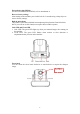
Camera Main Page Descriptions: Source: Information bar 1. Format: resolution of the current video stream 2. FPS: FPS of the current video stream 3. BitRate: bandwidth per second of the current video stream Brand Logo – Click to access the latest information from our website. Product name Image area Attention: Please change the streaming setting to HTTP if nothing appears in the image area.
Control panel 1. Camera direction: controls the direction of the camera (up, down, left, right, home position). Direction control. 2. Camera speed: controls the rotation speed of the camera from “1” (lowest) to “7” (highest). Rotation speed. Speed Angle/Sec.
3. Preset: presets the rotation points for the camera (16 points) 1. Click Set to enter the Preset Setting screen. 3. Control the camera direction. 2. Enter the name of the location. 4. Click Update to exit. 5. Select the number you need and click Go. The camera moves to the area automatically as set up by the selected number.
4. Tour: enables/disables the tour mode of the camera. The rotation points of the camera must be set up in advance. 1. Click Set to enter the Tour Setting screen. 2. Name the tour. You can set up 5 tour groups at maximum. 3. Dwelling time (sec.) at each tour point. 5. Click Update to Exit. 4. Select a preset location for the camera. 6. Click Enable to activate the tour function.
5. Pan: start/stop Camera panning. You can click “Start” button to make the camera move back and forth horizontally. Click “Stop” button to stop panning. 6. Alert: displays alert trigger This indicator flashes to warn you when a movement or alert is detected. Click to stop the flash. Alert trigger display ato Pan function Enable/ disable the alert message display Alert message display area 7. Alert Message: enables/disables the alert message display. Alert Message: displays the alert message.
8. Language: selects a UI language Two languages are available: English and Chinese. Selects a language 9. Camera Position: sets the position for display of the image Desktop: Normal image (display on the desktop; default value) Ceiling: Upside-down image Mirror: Mirror image Rotate 180: Mirrored and upside-down. Set the position for display of image.
10. View Size: selects the size of the image Select the size of the image from 0.5 to 4 times. Select an image size 11. Streaming: sets the video stream protocol (HTTP is recommended) The product provides three different video streaming protocols: UDP, TCP, and HTTP. HTTP is the most recommended because it allows the video stream to go through the firewall. (Refer to Setting/Basic Setting/Network/Streaming for more information). UDP: It provides the fastest but unreliable transmission service.
Select a video stream protocol 23
12. Brightness: adjusts video brightness Contrast: adjusts video contrast Press + (increase) or ﹣ (decrease) from the setting window to adjust the brightness or contrast of the image. Adjust brightness/contrast of the image 13. REC: executes the video recording function Click this button to start video recording and save the image file in the preset directory (C:\video). A red mark appears at the bottom left corner of the image when the recording function is running. Recording button Snapshot button 14.
15. Path: sets the save path and name for recorded images and snapshots. The filename is the recording date by default. You can identify the file by prefix of the filename. Click the Path field to select the folder to save the file. Save the path Pickup function Automatic Noise Suppression system 16. Audio On/Off: turns on/off the pickup function Click the button to mute the sound from the built-in microphone. A cross-out mark appears on the speaker icon to indicate the mute status. 17.
System setting System setting contains basic and application settings. The basic setting is executed for basic system information, transmission speed, audio/video code, user authorization, date/time, and IP filter, while the application setting is executed for event triggering definition and other relevant settings, definition of the motion detection area, firmware update, reset to factory default, and reboot of the machine.
Basic Setting >Video/Image Basic Setting > Video Image > Video Image Basic Setting > Video / Image > Video Image > 3GPP To view the camera image using a 3G cellular phone, click Enable to enable the 3GPP mode. (Note: When the 3GPP mode has been activated, all relevant parameters are set automatically and cannot be changed for the sake of compatibility). 3GPP mode To use the 3GPP function, the following requirements must be met.
4. Enter the link name. 3. Add a new link. 6. Select OK to save the setting. 7. Select this stream name to proceed with linking. 8. Select “Yes” to connect. 10. Loading the image. 9. Connecting. 28 5. Enter the IP address of the camera, e.g. rtsp://xxx.xxx.xxx.
11. Video stream screen .
Basic Setting > Video / Image > Video Image >Video Format You can select MPEG4 or MJPEG as the video format. It is recommended to select MPEG4 for real-time browsing to optimize the bandwidth. MJPEG is a good choice for the best resolution when video recording is required for collection of evidence. Select a video streaming format Basic Setting > Video / Image > Video Image >Video Resolution Generally speaking, selection of resolution is dependent on the bandwidth of the network you are using.
Basic Setting > Video / Image > Video Image >Frame per Second (FPS): With NTSC, you can choose 30, 15, 10, 7, 6, 5, 4, 3, 2, or 1 for video resolution With PAL, you can choose 25, 12, 6, 5, 4, 3, 2, 1 for video resolution. Select a FPS Basic Setting > Video / Image > Video Image >Video Quality You can select Fix Quality (resolution priority) or Fix Bitrate (fluency priority) at the same bandwidth. Five options are available for your choice: Best, Better, Normal, Fast, and Fastest.
Select GOP to update the speed. GOP provides users with the function to set the pages of the I Frame and P Frame to be transmitted in the MPEG4 mode. Basically, the I Frame page contains the entire picture and needs higher bandwidth, while the P Frame page only contains the parts that are different from the I Frame and needs lower bandwidth. Hence, when you need to transmit the pages without disruption in a normal network environment, you can set up a higher GOP.
OSD setting Brightness/contract adjustment Date, time, and text display 33
Basic Setting > Audio (Sound) Basic Setting > Audio > Audio (sound setting) Basic Setting > Audio > Audio > Audio Raw Format You can select No Audio or PCM. When you select No Audio, the sound transmission from the built-in microphone pauses. When you select PCM, the sound transmission resumes. The factory default is PCM.
Basic Setting > User(User) The administration of the camera can set up access privileges by administrator, operator, and viewer to ensure the security and control of the camera. The access privileges and setting steps are described as below. Basic Setting > User > User List (access privilege list) The access privileges of the administrator, operator, and viewer are listed as follows. The administrator has the right to define the privilege for each user depending on requirements.
User setting Change the privilege or password of a user. You cannot change the name of the user. Add a new user and set up a different privilege. Delete a user from the list. Log in the username, password and privilege as required. You can also define the PTZ control here. Basic Setting > User > User Setting (privilege setting) For special business situations, the product allows you to log in to browse without the need of keying in your username and password.
Basic Setting > Network (Network setting) Basic Setting > Network > Network (wired network setting page) Basic Setting > Network > Network > IP Assignment Cable network setting page DHCP setting: DHCP(Dynamic Host Configuration Protocol) is a protocol that enables automatic assignment of TCP/IP information to the client. Each DHCP client connects to the DHCP server to access its network setting information, including IP address, gateway, and DNS server. The IP address of the camera is 192.168.0.
Basic Setting > Network > Wireless (wireless network setting page) The wired network setting procedure shall apply where the LAN socket is connected to the network cable. Where wireless network is required, you need to remove the network cable after completing the wireless network setting and restart the machine.
Mode: Selection of the wireless networking mode 1. Infrastructure: Infrastructure networking mode The camera uses the wireless Access Point (AP) as the hub when it is in the infrastructure networking mode and connects to the network via the wireless AP. 2. AdHoc: Point-to-point networking mode The camera connects to other wireless devices via a wireless network when it is in the AdHoc point-to-point networking mode; i.e.
Network authentication type Authentication Type: Network authentication type 1. Open System: No encryption. 2. Shared Key: Security of data is highly protected by encryption during transmission. Note: Refer to the user setting instructions of your wireless IP sharer for more information.
Encryption options WEP Encryption: WEP encryption function When the base station (AP) to which you want to access has enabled the encryption function, you need to acquire the following information by accessing its encryption settings. You can use the computer equipped with wireless networking function to view the available wireless networks from the Windows system.
Encryption mode Encryption authentication type Encryption group WEP security mode: Select an encryption mode from the list. The format is “None” by default, indicating that the security function is disabled. Authentication mode: One of the following authentication modes is required when you select a WEP encryption mode from the security list. 1. 64 Bit (10 Hex chars) 2. 64 Bit (5 ASCII chars) 3. 128 Bit (26 Hex chars) 4.
The IP address of the camera is 192.168.0.20 by default when DHCP is “OFF”. When you select “DHCP ON” and access to the DHCP network environment, the camera will automatically send a DHCP packet to request an IP address. This IP address is assigned automatically from the DHCP server on the network. No additional settings are required for this page unless you need to change the network configuration. The DHCP status of the camera is “OFF” by default.
image transmission. However, video fragment or mosaics may occur due to poor transmission quality. Streaming port setting Basic Setting > Network > PPPoE (dial-up networking setting) PPPoE: Point-to-Point Protocol over Ethernet is a protocol that supports access to a high-speed wideband network using a PC and a wideband modem (such as xDSL, Cable, Wireless modem).
3. Key in the IP address of the camera and enter "PPPoE Setting" following the route Setting Basic Setting Network PPPoE. 4. Key in the xDSL "Username" and "Password" acquired from your ISP. Click Save to confirm the setting. 5. Where the ADSL modem and the camera is connected via a switch-hub, you can press “Reboot” or restart the machine manually to try PPPoE dialing when the setting of the camera has been completed. 6.
Basic Setting > Network > DDNS (Dynamic Domain Name Server Setting) The IP address (Ex. 210.168.0.22) is like a telephone number, while the website address is like a name in an address book. The DDNS allows the user to access the website by entering the name of the website without memorizing a bunch of cold numbers. When you apply for an Internet service, you will have at least one IP address from your ISP, which is either a fixed or dynamic one.
Basic Setting > Network > UPnP (Universal Plug and Play) If you connect your camera to a router, IP allocator, or wireless AP, your camera will possibly be blocked by the NAT and can’t be located on the Internet. To penetrate into the firewall, activate the supportive item- UPnP. The Link URL shows the external IP address and the port of the router. Enter the IP address in the Internet Explorer to penetrate the NAT.
To activate the UPnP function in Windows OS: Ex: Windows XP: 1. Windows component installation. 1. Click Control Panel 2. Click Add/Remove Programs 4. Click Networking Services 6. Check UPuP User Interface 5. Click Detail 3. Click Add/Remove Windows Components 2. Open Windows firewall option 2. Click Exceptions 1. Click Windows Firewall in the Control Panel 3. Check UPnP Configuration.
3. View the connection device using Network Neighborhood 1. Open Network Neighborhood 2. The LAN camera appears. Double-click to access the main page. Basic Setting > Network > SMTP Server (mail server setting) The camera is able to transmit images to a particular email address when a motion detection event occurs or a sensor is triggered. To use this function, a mail server setting of the camera is required.
Basic Setting > Network > Samba The camera is able to upload the snapshots to a specified shared folder when an event is triggered. To use this function, the setting of Samba setting is required. Options: Active: Enable/Disable Samba Authentication: Enable/Disable Username: the username Password: the password Path: specify the IP address of the computer you want to share with and the file name, i.e. 192.168.0.X/xxx Shared Folder Size (MB): the total capacity of the folder.
Basic Setting > Network > Notification Of IP Address Change (IP address change notice) This setting is not necessary for a fixed IP. For a dynamic IP, you need to update the IP address every time you connect to the Internet to access the camera. This setting allows you to update the IP address by the automatic notification of IP address change. Choose one of the following three notice options to update the IP address: 1.
Notification setting 52
Basic Setting > Date/Time (date/time setting) Date/Time setting Basic Setting > Date/Time > Server Time (the date/time of the server) Basic Setting > Date/Time > PC Time (the date/time of your PC) Basic Setting > Date/Time > Time Setting (date/time setting) There are three ways to synchronize the time. 1. Synchronize the time with PC’s time: The preset method of time synchronization of the camera time with your PC time. 2.
Basic Setting > IP Filter This function filters IP addresses and is able to allow and deny visits from particular addresses/target addresses. IP filter setting Basic Setting > IP Filter > General IP Filtering: enables/disables the IP filter Policy: allows/denies access Basic Setting > IP Filter > Filter IP Address (Overview of the set IPs) Add: enter the IP address you want to allow or deny the access of in the front field.
Application Setting Application Setting > Event (event trigger setting page) This camera is equipped with intelligent security management functions. It ensures security monitoring by allowing user to define “trigger events” based on particular times and situations, and set the camera response to the event.
Add Event : Add Event setting page Options: • General: Name: Name the trigger event here. • Response to event trigger: the time setting of the trigger event Always: Always monitoring During time: Check the date you want to monitor (Sun~Sat) and the duration of monitoring here.
Add Schedule: Add Schedule setting page The Add Event setting page and the Add Schedule setting page is basically the same except that the Add Schedule setting page does not have the option “Trigger by” to indicate the sources of the trigger event. Click Save to save and activate your settings when you complete setting. Delete: delete the event cluster setting. Modify: modify the event cluster setting.
The default status of the digital input pin is set as “Normal Open”, but users can change it to “Normal grounded” by setting the page “Setting->Application->Event->Trigger”: 1. When alarm input is set to be “Normal Open”, then the external device connected to alarm input pin should be in open status. So when the external device is triggered to close status, the alarm input pin will be triggered. 2.
Application Setting > Event > Event Servers (setting for uploading trigger event file to the server) Here you can perform a complete setting for uploading files to the server. Please set servers (SMTP, FTP, SAMBA…etc) in the Event Server setting by the instructions below: Click Add Ftp to go to the setting page and enter the information of the FTP server you specified.
Click Add Http to go to the setting page and enter the information of the HTTP server you specified.
ProxyPort: Proxy server port ProxyLogin: Proxy server log-in name Proxy Password: Proxy server log-in password Click Add Tcp to go to the setting page and enter the information of the TCP server you specified.
Application Setting > Motion Detection You can open the setting frame by clicking on the area to monitor. To move area to monitor, drag the area with your mouse; to adjust the size of the frame, drag the arrow to adjust after you move the mouse to the edge of the area and left-click; There are 3 frames available for setting. You may adjust the sensitivity of the area by entering the sensitive degree in the “Sensitive” field. “1” is least sensitive, ”100” is extremely sensitive.
Application Setting > Firmware upgrade Firmware upgrade page Contact your dealer for more information about firmware upgrade. The sales representative will transmit the latest version to you via e-mail. When you receive the firmware, decompress the file (uImage.gz) to your PC and follow the steps below to execute the upgrade. Important! Read Carefully!! 1. Close all active applications on your PC. 2. Select “Firmware Upgrade” 3. The Firmware Upgrade Setting page appears.
Click Browse… to select the location where the firmware file is stored. 4. Click submit. 5. The auto upgrade runs. The Upgrade Status shows the progress of the upgrade. When the firmware upgrade has been completed, the machine reboots automatically. Reconnect to the server after 60 seconds. Note: The new firmware is burned into the Flash ROM during the upgrade, so you must take care during the process and make sure it is not interrupted during the operation.
Application Setting > Factory Default You can use this function to reset to factory default, but all changes, including the IP address, you have made are deleted. Reset to factory default Factory Default: Reset to factory default. Warning dialog for rest to factory default Resets all parameters, except the IP parameters: You can use this function to reset to factory default.
Backup: Data backup Back all parameters: Back up all changes you have made. When you click Backup, a file download window appears. Back up the file named param.bin (Attention: Don't change the file name; otherwise, the backup may fail.) File backup Restore backup parameters: You can select this function to restore the changes you have made. To do this, click Browse… to select a backup file and click submit to confirm the restoration.
Application Setting > Reboot You can enable this function for the camera to reboot automatically.
Attachment A: External Alarm In addition to the motion detection executed by the internal software application, the product can connect to external infrared detectors, beepers, and smoke detectors. For more information about these external devices, contact to your local retailer, dealer or installation service provider. This product provides a standard Alarm I/O for you. This product is provided with 2 sets of digital inputs and 1 set of digital outputs.
External Alarm I/O Circuit Diagram Pin 1 Warning! The alarm will be triggered when alarm pin 1 & 2 are formed as a short circuit. Please do not connect the electric voltage or current into alarm input pin for the electronic current might burn the product. Pin 2 Warning! The alarm will be triggered when alarm pin 2 & 3 are formed as a short circuit. Please do not connect the electric voltage or current into alarm input pin for the electronic current might burn the product.
Attachment B: Bandwidth Estimation Since the FPS is dependent on the bandwidth of the camera, the relation between the size of an image file and the bandwidth is always the major concern of the system construction engineer. The table below shows the relation between the resolution and size of an MJPEG file in the NTSC system.
Attachment C: Troubleshooting and FAQs Question Answer and Solution Function What encoder and decoder The camera uses MJPEG or MPEG4 compression technology to are used by the camera for provide quality images. MJPEG is a standard image compression sounds and images? technology applicable to different browsers without the need to install additional software. MPEG4 is a next-generation image compression standard and can provide high image quality at low bandwidth.
Internet Explorer does not display the camera screen correctly. IP Finder cannot store network parameters. • The anti-virus applications on the PC or the firewall might block the IP Finder from execution. If you can not execute the IP Finder, please disable your anti-virus applications or firewall. Please be sure that the version of your Internet Explorer is 6.0 or later. Should you have any difficulties, please log on the Microsoft website to update your browser. Microsoft website: http://www.microsoft.
computer. sure that your Internet Explorer security is properly set (the default value is moderate). Re-connect to the camera main page and download the file again. Incomplete download or installation of the camera ActiveX control is the major reason for this problem. Check the security setting of your Internet Explorer. Close and re-open Internet Explorer, and enter the main page to see if you can log in. Change the IE security setting to allow downloading unsigned ActiveX control.
I can't control the camera to move up, down, right, or left smoothly. Delay might occur when you are accessing a video stream and remotely moving the camera horizontally. Where significant delay is identified when you move the camera horizontally or vertically deactivate the audio streams and/or reduce the size of the video stream... Camera Image Quality Camera has a problem focusing. • The lens might be contaminated with dust, fingerprints, or other dirt.