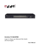
IntraCore® IC3624PWR Layer 2+ Power over Ethernet (PoE) Switch with Dual Gigabit User’s Manual
IntraCore® IC3624PWR Layer 2+ Power over Ethernet (PoE) Switch with Dual Gigabit User’s Manual Asanté Technologies, Inc. 2223 Old Oakland Road San Jose, CA 95131 USA SALES 800-662-9686 Home/Office Solutions 800-303-9121 Enterprise Solutions 408-435-8388 TECHNICAL SUPPORT 801-566-8991: Worldwide 801-566-3787: Fax www.asante.com/support support@asante.com [Default IP Address: 192.168.0.1] [Default username: root [Default password: Asante ] ] Copyright © 2004 Asanté Technologies, Inc.
Table of Contents Table of Contents...........................................................................................................................................................3 Chapter 1: Introduction...................................................................................................................................................7 1.1 Features ..................................................................................................................................
3.7 Applying Power ..................................................................................................................................................16 3.8 Ethernet Cabling.................................................................................................................................................17 3.9 Connecting to the Console Port..........................................................................................................................17 3.9.
6.3 Advanced Switch Configuration..........................................................................................................................41 6.3.1 VLAN Management......................................................................................................................................42 6.3.2 Link Aggregation ..........................................................................................................................................45 6.3.3 Port Monitoring........
C.2 Pin Assignments for 1000BaseT Pin .................................................................................................................82 C.3 Cable Testing for Existing Category 5 Cable .....................................................................................................83 C.3.1 Adjusting Existing Category 5 Cabling to Run 1000BaseT..........................................................................83 C.4 Fiber Standards .............................................
Chapter 1: Introduction The IntraCore IC3624PWR Layer 2+ Power over Ethernet (PoE) with Dual Gigabit (IC3624PWR) is a product you can use to build your next generation network. The IC3624PWR device uses Layer 2+ technology and has 24 ports for 10/100/1000BastTX Fast Ethernet with 2 combination ports for added 10/100BaseT Gigabit Ethernet. Use the advanced features on the IC3624PWR switch to deploy Voice over IP (VoIP) telephones, cameras and wireless access points.
1.1.2 Performance The IC3624PWR switch uses a wire-speed, non-blocking switching fabric. • Wire-speed Gigabit switching (1,488,000 pps) and Fast Ethernet switching (148,800 pps) • Non-blocking 8.8 Gbps switch fabric 1.1.3 Management • Web browser • Telnet (multiple sessions) • Console • SNMP v1 and v2c • RMON Groups 1, 2, 3 and 9 1.2 Network Management Options The IntraCore IC3624PWR provides both local and remote management.
Chapter 2: Network Planning This chapter gives an overview of switch management, including the methods you can use to manage your IntraCore IC3624PWR Managed Switch. Topics include: • Management Access Overview • SNMP Access • Protocols 2.
Management Method Advantages Disadvantages Administration Console Out-of-band access through direct cable connection eliminates network bottlenecks, crashes, and downtime Must be near switch or use dial-up connection Not convenient for remote users No IP address or subnet is needed Not available using a GUI Menu or CLI based HyperTerminal access to full functionality (standard Microsoft Windows 95/98/NT/2000 operating systems) Web Browser or Telnet Access from any location through the switch’s IP
2.2.1 Protocols The IC3624PWR switch supports the following protocols: • Virtual terminal protocols, such as Telnet • SNMP • Virtual Terminal Protocols A virtual terminal protocol is a software program, such as Telnet, that allows you to establish a management session from a Macintosh, a PC, or a UNIX workstation. Because Telnet runs over TCP/IP, you must have at least one IP address configured on the IC3624 switch before you can establish a connection.
Chapter 3: Hardware Installation and Setup This chapter describes the procedures for rack-mounting, connecting the cables, and powering up the IntraCore IC3624PWR PoE switch at your site. 3.1 Installation Overview 1. Follow these steps to install the IntraCore IC3624PWR PoE switch: 2. Open the box and check the contents. For a complete list of the items included with the switch see “Equipment Checklist” section later in this chapter. 3.
3.3 Site Requirements Consider the following site requirements for proper installation. 3.3.1 Environmental Requirements Choose a clean, dry, dust-free area location. Avoid direct sunlight, heat sources, or areas with high levels of electromagnetic interference. Failure to observe these limits may cause damage to the switch and may void the warranty. 3.3.
3.4 Preparing for Installation Switches can be mounted in a standard 19-inch equipment rack or on a flat surface. Follow these general precautions when planning your equipment locations and connections. The site needs the following: • Centrally located to the devices you want to link • Near a power outlet.
3.5.1 Recommended Tools You need the following tools and equipment (not included) to install the switch into an equipment rack: • Flat head screwdriver • Phillips head screwdriver • Four mounting screws for each device you plan to install in a rack (not included with the switch) • Antistatic mat or foam 3.6 Installing the Switch The switch can be mounted in a standard 19-inch equipment rack or place on a desktop or shelf. Mounting instructions for each type of site follow. 3.6.
Warning: Make sure you support the switch until all the mounting screws for each bracket is secured to the equipment rack. Failure to do so could cause the switch to fall, which may result in personal injury or damage to the switch. When installing multiple switches, mount them in the rack, one below the other, in any order. When installation is complete turn to the “Applying Power” section. 3.6.
3.8 Ethernet Cabling The cables you need are determined by the existing equipment. To ensure proper operation when installing the switch into a network, make sure that the current cables are suitable with either 10/100BaseTX, 10/100/1000BaseT or 1000BaseT operation.
3.9.1 Wiring Map for Serial Cable The following table describes the serial cable wiring information.
Chapter 4: Connecting Network Devices The switch is designed to interconnect multiple segments (or collision domains). It can be connected to network cards in PCs and servers, and to hubs, routers, or other switches. 4.1 Twisted-Pair Devices Each device requires an unshielded twisted-pair (UTP) cable with RJ-45 connectors at both ends. Use Category 5 for 100BaseTX connections, and Category 3, 4 or 5 for 10BaseT connections. 4.1.
4.1.3 Network Wiring Connections The punch-down block is an integral part of many of the newer equipment racks. It is actually part of the patch panel. Instructions for making connections in the wiring closet with this type of equipment follows. Attach one end of a patch cable to an available port on the switch, and the other end to the patch panel. Attach one end of a cable segment to the back of the patch panel where the punch-down block is located, and the other end to a modular wall outlet.
The following table lists the LEDs and describes the status lights. LED Condition Status Fast Ethernet On/Green The port has a valid 100 Mbps link. Flashing indicates activity. On/Amber The port has a valid 10 Mbps link. Flashing indicates activity. On/Green The port has a valid 100 Mbps or 1000 Mbps link. Flashing indicates activity. Gigabit Ethernet 4.3 Connectivity Guidelines When adding to your network, follow the connectivity rules listed in the manuals for these products.
4.4 Cable Labeling and Connection Records When planning a network installation, it is essential to label and record where each cable is connected. This helps you locate inter-connected devices, isolate faults, and change your topology. To manage the physical implementations of your network, follow these guidelines: • Label the opposing ends of each cable. • Draw a map of the location of all network-connected equipment using your building’s floor plans.
Chapter 5: Configuring the Switch This chapter takes you through the steps required to initially connect the switch to a console, set up initial passwords, configure an IP address, and restore factory defaults. For complete information about configuring, monitoring, and maintaining your switch, refer to the System Management Guide. 5.1 Connecting to the Switch The switch includes a built-in network management agent.
5.2 Direct Access Direct access to the switch console is achieved by connecting the switch’s console port to a VT-100 or compatible terminal or to a PC, Apple Macintosh, or UNIX workstation equipped with a terminal-emulation program. This connection is made using the null-modem cable supplied with the switch.
The following screen appears. 1. Enter a name for this connection. 2. Click OK The following screen appears. 1. In the drop down box labeled Connect Using:, click the arrow and choose the desired COM port. (In the example below, COM1 is the port selected.) 2. Click OK.
Connection Settings The port settings are as follows: Baud Rate: 9600 Data Bits: 8 Parity: None Stop Bits: 1 Flow Control: None 1. Enter the settings. 2. Click OK. 5.3 Initial Logon The switch offers a Command Menu Interface (CMI), which is a menu-driven method for managing the switch, as well as a Command Line Interface (CLI), which uses text input to manage the switch. Unless otherwise noted, the screen examples in this chapter are from the CLI.
To use the arrow keys when attached to the User Interface using a Telnet Session, under the terminal pull down menu choose Properties and activate the VT100 Arrows option.
Chapter 6: Using the Interface The main menu displays available sub-menus. The letter within square bracket of each menu option can be typed to directly choose that option. From the main menu there are seven menu items to choose from: • General Information • Basic Configuration • Advanced Switch Configuration • Statistics • Switch Tools Configuration • Save Configuration • Run CLI To logout of the user interface, press the Ctrl and D keys at anytime during your telnet session.
IntraCore IC3624PWR Layer 2 PoE Switch with Dual Gigabit
The following table describes the areas you see from the General Information screen.
6.2.1 Administration Configuration From the Admin Configuration screen, you can enter system-related information for reference such as System Name, System Location, and System Contact Information. Map: Main Menu->Basic Configuration Menu->Administration Configuration Note: The system Description and Object ID are not configurable.
6.2.2 IP Configuration All hosts that run IP must have a unique IP address. An IP address is a logical address that is independent of a host’s hardware. IP addresses are 32 bits long. Map: Main Menu->Basic Configuration Menu->IP Configuration From the IP Configuration screen you can manage the IP related information of the system.
Configure the switch by adding the SNMP host agent to the host table in order to participate in the SNMP community.
6.2.3.1 SNMP Management Configuration The SNMP Configuration screen lists all SNMP managers and associated information. There are two default community strings, private and public. Read-only is allowed with public mode and read-write is allowed in private mode. You can change the community strings to meet your network requirements.
6.2.3.2 Trap Configuration All hosts in community strings with TRAP privileges are notified when a trap condition occurs. Map: Main Menu->Basic Configuration Menu->SNMP Configuration->Trap Configuration 6.2.3.3 Individual Trap Configuration When this feature is enabled the system generates an SNMP trap when a host authorization failure occurs. The failure occurs when a host tries to gain access to the system and the host’s IP address is not in the SNMP host table.
Port Link Down Trap When this feature is enabled, the system generates an SNMP trap upon a port link down. The failure occurs when a link is disconnected. You can enable or disable each port independently. Enable The system generates a SNMP trap upon a port link down Disable The port link down trap is not generated upon a port link down As authentication failure trap, all hosts in community strings with TRAP privileges are notified when a trap condition occurs.
6.2.4 Port Configuration In the Basic Port Configuration menu, you can set the port admin status, mode, and flow control. The following is an example from the GUI interface. Map: Main Menu->Basic Configuration Menu->Port Configuration 6.2.5 System Security This screen allows you to enable or disable the web, SNMP, and/or telnet interfaces, as well as change the user name and password. User names and passwords are case sensitive and can be up to 12 characters long.
6.2.6 Forwarding DB Use the Forwarding Database menu to view the dynamic MAC addresses in the address database. When addresses are in the database, the packets are forwarded directly to the specified ports. You can display addresses in the table by port, VLAN, or MAC address. Use the Static Addresses Table to specify Media Access Control (MAC) addresses for specific ports that you do not want to be purged from the table by the aging function.
There are four commands available on this menu. Static Address Table Display and configure the static MAC address table. Display MAC Address By Port Display MAC address table for a specified port Display MAC Address by MAC Display MAC address in order of MAC address. Display MAC Address by VID Display MAC address table for a specified VLAN ID. The following figures show an instance of Static Address Table. There are 3 entries on the table. Two commands are available to add or remove an entry.
There are four commands on this menu. The example below is from the GUI interface. Map: Main Menu->Basic Configuration Menu->SNTP Configuration Set SNTP Server IP Use to set Simple Network Time Protocol, enter SNTP server IP to get into it Set SNTP Interval Use to set up SNTP polling interval, for example 1min Set Time Zone Use to set the time zone Pacific Set Daylight Saving Use to set up the daylight saving 6.2.
Map: Main Menu->Basic Configuration-> ARP Table 6.3 Advanced Switch Configuration The Advanced Switch Configuration screen allows you to configure several advanced system-related settings. Map: Main Menu->Advanced Switch Configuration There are ten submenus on the Advanced Switch Configuration screen.
6.3.1 VLAN Management A virtual LAN (VLAN) is a switched network that is segmented by function, project team or application, without regard to the physical locations of the users. Any switch port can belong to a VLAN, and unicast, broadcast, and multicast packets are forwarded only to stations in the VLAN. Each VLAN is considered a logical network, and packets destined for stations that do not belong to the VLAN are forwarded.
Map: Main Menu->Advanced Switch Configuration->VLAN Management The following table describes the six options available from the VLAN Management submenu. Create VLAN: Create a new VLAN; a unique ID must be given. Delete VLAN: Delete a VLAN ID. The entire setup for this VLAN will be erased. Configuration VLAN Member: Configure the member of a VLAN Set Port Configuration Set the configuration of a specified port Set GVRP Status: Enable or disable the GVRP switch-wide.
Follow these steps to configure a VLAN member: 1. Select Configuration VLAN Member 2. Give the corresponding VLAN ID 3. Modify the VLAN members 4. Click Apply. Follow these steps to set GVRP Status: 1. Select Set GVRP Status 2. Choose E to enable and D to disable Follow these steps set Management Status: 1. Select Set Management Status 2. Choose U to enable and D to disable. 6.3.1.2 VLAN Port Configuration Use this sub menu to individually configure VLAN ports.
• Set GVRP Status • Quit to previous menu Set Port VID: Set PVID of a port. Set Frame Type: Set the acceptable frame types, All or Tagged Only. When the Tagged Only is selected, all non-tagged packet are dropped. Set GVRP Status: Enable or disable the GVRP of a port. Note: When you delete an existing PVID the switch uses the default PVID1. 6.3.2 Link Aggregation The Trunk Configuration screen is used to set multiple links between switches to work as one virtual link (aggregate link).
6.3.2.1 Set Port Priority The default system priority is the same in all ports. To set up a port with a different priority in the link aggregation, use the Set Port Priority.
6.3.3 Port Monitoring The Port Monitoring screen is used to can designate a port for monitoring traffic from one port configured on the switch. The switch monitors the network activity by copying all traffic from the specified monitoring sources to the designated monitoring port to the attached network analyzer. Map: Main Menu->Advanced Switch Configuration->Port Monitoring There are five options available from this menu. Set Monitoring Port: Set the monitoring port.
• Global Commands: • Enable/Disable Global MSTP • Set MSTP Protocol Version • Set MSTP Configuration Name • Set MSTP Revision Level • CIST Configuration • CIST Basic Port Config • CIST Advanced Port Configuration • MSTP Instance Configuration • Designated Topology • Regional Topology • Quit to previous menu IntraCore IC3624PWR Layer 2 PoE Switch with Dual Gigabit
The following tables define the global information that is access and configure through this submenu. Global MSTP Status: The status of global multiple spanning tree protocol. Enable indicates that MSTP is running. Disable indicates that MSTP is not running. Protocol Version: The protocol can be one of three versions, SPT (Spanning Tree), RSPT (Rapid Spanning Tree), and MSTP (Multiple Spanning Tree).
6.3.4.1 CIST Configuration Use this submenu to configure the Common Internal Spanning Tree (CIST).
6.3.4.2 CIST Basic Port Configuration Set the port priority, the path cost for each port and enable or disable the port STP status to increase the network efficiency.
6.3.4.3 Advanced CIST Port Configuration Set the port edge status, the port-to-port status, and restart port migration to prevent the wrong link. Map: Main Menu->Advanced Switch Configuration->MSTP Configuration->CIST Configuration 6.3.4.4 MSTP Instance Configuration Use the MSTP Instance Configuration screen when configuring a small tree in the MSTP. One Instance can have more than one VLAN. In this page, you can add, remove VLAN or remove, for the MST Instance and Instance Port configuration.
Map: Main Menu->Advanced Switch Configuration->MSTP Configuration->MSTP Instance Configuration IntraCore IC3624PWR Layer 2 PoE Switch with Dual Gigabit
6.3.4.5 Designated Topology Information Use this screen to view topology information, the status of the links and designated root, bridge and port numbers.
6.3.4.6 Regional Topology Information This page shows regional topology information.
6.3.5 Access List Configuration There are seven functions for access control. Map: Main Menu->Advanced Switch Configuration->Access List Configuration Classifier Classifier selects packets stream based on the value of combination of one or more header fields such as source IP address, destination IP address, DS field, protocol ID, source port and destination port numbers, and others. Classifier Group A show group status and allows you to join, remove and set group names.
6.3.5.1 Classifier Configuration Menu Use this submenu to create, delete and modify classifier fields. Map: Main Menu->Advanced Switch Configuration->Access Control->Classifier Configuration Menu Three commands are available in this screen.
The following describes the classifier fields.
6.3.5.2 Classifier Group Use this submenu to create or delete classifiers, join classifiers, remove, classifiers, set classifier group names. 6.3.5.3 In Profile Action From this screen you can create, delete, and modify the action for the different in-bound profiles.
Three options are available from the In-Profile Action submenu. • Create In-Profile Action • Delete In-Profile Action • Modify In-Profile Action • In Profile Action There are four options available when using the In-profile action menu: Drop: Shows the number of dropped packets Policed-dscp: Changes TOS -DS (first 6 bits) field value Policed-precedence: Changes TOS-precedence (first 3 bits) field value Policed-cos: Changes 802.
Three options are available from this screen. • Create No-Match Action • Delete No-Match Action • Modify No-Match Action • No-Match Action is the same as In-Profile Action. No-match action only supports 81 entries. 6.3.5.5 Out Profile Action From this screen you can create, delete, and modify the action for the different out-bound profiles. Map: Main Menu->Advanced Switch Configuration->Access Control->Out Profile Action Three options are available in this menu.
Drop: Number of dropped packets Policed-dscp: Changes TOS-DS (first 6 bits) field Committed rate: Configures committed rate to determine how traffic flow is allowed to pass. The packet is considered in-profile if it conforms to the bandwidth profile, out-profile otherwise. Burst size: Sets the burst size of a full bucket. When the token level is below the threshold value this indicates there is no available bandwidth (Note: Threshold value is 2KB) 6.3.5.
6.3.5.7 Policy Use this submenu to create, delete, enable or disable, show status or sequence and update the policies for the different ports. A policy may associated with classifier, in-profile, no-match, out-profile, port list, and sequence. Classifier and port list are necessary for a policy.
6.3.6.2 Scheduling Method Use this submenu to set the QoS scheduling method and the traffic class-weight mapping. Map: Main Menu->Advanced Switch Configuration->Quality of Service Configuration->Scheduling Method 6.3.7 Storm Control Storm control protects connected Ethernet ports by controlling traffic rates during periods of high volume. When the local device detects excessive traffic at its end, it can notify the link or the remote device by sending a pause frame.
6.3.8 802.1 Port Based Access Control Use this menu to view status of the ports and to set port specific values Map: Main Menu->Advanced Switch Configuration->802.1 Port Based Access Control Configuration Use this menu to set 13 functions.
6.3.9 IGMP Snooping In networks where multimedia applications generate multicast traffic, Internet Group Multicast Protocol (IGMP) reduces unnecessary bandwidth usage by limiting traffic forwarding that is normally broadcast throughout network. Enabling IGMP allows individual ports to detect IGMP queries, report packets, and manage IP multicast traffic through the switch. Map: Main Menu->Advanced Switch Configuration->IGMP Snooping There are four options available through this menu.
You can configure the switch to use Internet Group Management Protocol (IGMP) snooping in subnets that receive IGMP. IGMP snooping constrains multicast traffic at Layer 2 by configuring Layer 2 LAN ports dynamically to forward multicast traffic only to those ports that want to receive it. 6.3.9.1 Show IGMP Snooping VLAN Filter Table Set up the VLAN that you do not want to be snooping in the set VLAN Filter Table menu. Show the results of your configuration using this feature.
6.3.9.2 Show Router Port Table This page shows the ports in some VLANs that are connected to the router. You can snoop the package from router side in these ports. Map: Main Menu->Advanced Switch Configuration->IGMP Snooping->Show Router Port Table 6.3.10 Power over Ethernet Power-over-Ethernet (PoE) eliminates the need of 110/220 VAC power source to Wireless Access Points and other devices on a wired LAN.
6.3.10.1 PoE Port Configuration Power over Ethernet provides power to connected IEEE 802.3af-compliant powered devices from all 10/100 Ethernet ports if the switch detects that there is no power on the circuit. Use this screen to configure individual ports. Map: Main Menu->Advanced Switch Configuration->Power Over Ethernet->PoE Port Configuration Two functions provides for the PoE control. • Port Configuration • Global Configuration 6.3.10.1 PoE Port Configuration Admin.
6.3.10.2 PoE Global Configuration Globally configures switch to use PoE to provide power to connected IEEE 802.3af-compliant powered devices from all 10/100 Ethernet ports if the switch detects that there is no power on the circuit. Map: Main Menu->Advanced Switch Configuration->Power Over Ethernet->Global Configuration Power Usage: Sets the power usage threshold for sending a trap. Management Method: Sets the action to take when the power sink over the power budget.
6.4 Statistics Use this submenu to view statistics about the switch. Map: Main Menu->Statistics You can view the entire switch, select individual ports, refresh the screen to view current statistics or view statistics since the last reset.
6.5 Tools This screen enables you to manage and monitor the PoE Switch. Map: Main Menu->Tools This page has seven submenus: • TFTP Software Upgrade • Configuration File Upload or Download • System Reboot • System Log • Ping 6.5.1 TFTP Software Upgrade This menu enables you to upgrade your switch to the new software release. Once the IP address of the TFTP and the name of the new software image file are properly configured, you can upgrade the software with command on this menu.
The following procedure gives the steps to follow when using the web interface. The process is similar with either the CMI or CLI interfaces. 1. Go to Main Menu> Switch Tools Configuration> Software Upgrade Menu>TFTP Software Upgrade. 2. Set up the IP address and Image File Name. 3. Verify information such as the IP address for the TFTP Server and the file name of the new software image. 4. Verify the TFTP server and IP connection between server and switch are working properly. 5. Select Upgrade Image.
There are four submenus from this screen. Set TFTP Server IP Address Enter the server IP address to get the TFTP server Set Configuration File Name Enter the file name that you want to configuration Upload Configuration File Upload your configuration file Download Configuration File Download configuration file from TFTP server 6.5.3 System Reboot Use this submenu to establish the different types of system rebooting process.
6.5.5 System Log Use this submenu to observe system behavior. You can clear the system log by selecting Clear System Log.
6.6 Save Configuration Use this submenu to save the changed settings to the Flash memory after making any changes to the screens within the console interface. Map: Main Menu->Tools->Save Configuration to Flash To save the configuration to Flash memory select Save Configuration and then press either ‘Enter’ or ‘Y’. 6.7 Run CLI Use this submenu to configure the switch using the command line interface (CLI). To return to the menu-driven interface type “exit”.
Appendix A: Basic Troubleshooting In the event the switch does not operate properly, follow the troubleshooting tips below. F you need more help contact Asante technical support at www.asante.com/support. A.1 Diagnosing Switch Indicators Refer to the following troubleshooting chart for information about the diagnostic LEDs. Problem Possible Solutions The Power LED is not lit. LED will turn off during system initialization. Check the power connection.
Caution: The management agent can accept up to four simultaneous Telnet sessions. If you are at maximum number of sessions, an additional Telnet connection can not log into the system.
Appendix B: Specifications The sections below list the features and product specifications for the IntraCore IC3624PWR PoE switch.
L2+ Switching Virtual LANs IEEEE 802.1q, 256 VLANs Spanning Tree IEEE 802.1d (STP), IEEE 802.1s (multiple), IEEE 802.1w (rapid reconfiguration), fast link Flow Control IEEE 802.3x Link Aggregation IEEE 802.3ad, LACP, up to 6 trunks Authentication IEEE 802.1x per port access control Quality of Service IEEE 802.1p DiffServ and IP ToS Power over Ethernet Up to 15.4 watts per 10/100 port; 180 watts total Management Features In-Band Telnet, HTTP or SNMP manager.
Appendix C: Cables and Pin Assignments This Appendix describes the information on 10BaseT/100BaseTX, 1000BaseT, and testing for existing Category 5 cables. C.1 Twisted-Pair Cable and Pin Assignments For 10BaseT/100BaseTX connections, a twisted-pair cable must have two pairs of wires. Each wire pair is identified by two different colors. For example, one green wire and another green with white stripes. You must attach an RJ-45 connector to both ends of the cable.
Note: The “+” and “-” signs represent the polarity of the wires that make up each wire pair. C.1.2 Straight-Through Wiring If the twisted-pair cable is to join two ports and only one of the ports has an internal crossover (MDI-X), the two pairs of wires must be straight-through. (When auto-negotiation is enabled for any RJ-45 port on this switch, you can use either straight-through or crossover cable to connect to any device type.
The table below shows the 1000BaseT MDI and MDI-X port pinouts. These ports require that all four pairs of wires be connected. Note that for 1000BaseT operation, all four pairs of wires are used for both transmit and receive. Use 100-ohm Category 5, 5e or 6 unshielded twisted-pair (UTP) or shielded twisted-pair (STP) cable for 1000BaseT connections. The length of any twisted-pair connection must not exceed 100 meters (328 feet).
TIA 568-B allows the use of 50/125 micron multimode optical fiber in both the horizontal and backbone in addition to the types listed above. All optical fiber components and installation practices must meet applicable building and safety codes.
Appendix D: FCC Compliance and Warranty Statements D.1 FCC Compliance Statement This equipment has been tested and found to comply with the limits for a Class A digital device, pursuant to part 15 of the FCC Rules. These limits are designed to provide reasonable protection against harmful interference when the equipment is operated in a commercial environment.
D.3 IntraCore Warranty Statement Products: IntraCore IC3624PWR Duration: 3 years Advanced Warranty Replacement: United States: Second Business Day Other Countries: See your local distributor or reseller. Asante Technologies warrants (to the original end-user purchaser) the covered IntraCore products against defects in materials and workmanship for the period specified above.
Appendix E. Online Warranty Registration Please register the switch online at www.asante.com/support/warranty/index.html. By doing so, you’ll be entitled to special offers, up-to-date information, and important product bulletins.