FriendlyNET® GX5-424W 24+4 WebManaged™ Gigabit Ethernet Switch User’s Manual
FriendlyNET® GX5-424W 24+4 WebManaged Gigabit Ethernet Switch User’s Manual Asanté Technologies, Inc. 821 Fox Lane San Jose, CA 95131 USA SALES 800-662-9686 Home/Office Solutions 800-303-9121 Enterprise Solutions 408-435-8388 TECHNICAL SUPPORT 801-566-8991: Worldwide 801-566-3787: FAX www.asante.com support@asante.com © 2003 Asanté Technologies, Inc. All rights reserved.
Asanté FriendlyNET GX5-424W User’s Manual 3
Table of Contents Chapter 1 Introduction.................................................................................................................................. 5 Features.......................................................................................................Error! Bookmark not defined. Chapter 2 Unpacking and Installation ......................................................................................................... 6 Unpacking ............................................
Chapter 1 Introduction Congratulations on the purchase of the FriendlyNET GX5-424W 24+4 WebManaged Gigabit Ethernet switch. This device integrates 1000 Mbps Gigabit Ethernet, 100 Mbps Fast Ethernet, and 10 Mbps Ethernet network capabilities in a highly flexible package. The versatile GX5 uses its on-board CPU to take the complexity out of configuring a workgroup.
Chapter 2 Unpacking and Installation This chapter provides unpacking and installation information for the GX5-424W switch. Unpacking Open the shipping cartons of the GX5-424W switch and carefully unpack its contents.
Connecting Network Cable The GX5-424W switch supports 10 Mbps Ethernet or 100 Mbps Fast Ethernet and runs both in half and full duplex mode using Category 5 cable. The GX5-424W switch also supports 2 port 1000 Mbps Gigabit Ethernet that runs in autonegotiation mode and 10 Mbps Ethernet or 100 Mbps Fast Ethernet that runs both in half and full duplex mode and 1000 Mbps Gigabit Ethernet runs in full duplex mode using four pair of Category 5 Cable. These RJ45 ports support Auto-Uplink.
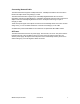
Chapter 3 Identifying External Components This chapter describes the front panel, rear panel, and LED indicators of the GX5-424W switch. Front Panel The figure below shows the front panel of the GX5-424W switch. Figure 3. Front panel of the FriendlyNET GX5-424W 24+4 WebManaged switch. LED Indicator Comprehensive LED indicators display the status of the switch and the network (see the following “LED Indicators” chapter).
AC Power Connector This three-pronged connector supports the power cord. Plug in the female connector of the provided power cord into this connector, and the male into a power outlet. Supported input voltages range from 100–240 VAC at 50–60Hz. Reset to Factory Default This button resets all the settings back to the factory default, including: • IP Address: 192.168.123.253 • Password: admin Note: Be sure to record the settings of your device.
Chapter 4 Understanding LED Indicators The front panel LEDs provide instant status feedback, helping to monitor and troubleshoot when needed. Figure 5. LED indicators on the GX5-424W switch. Power and System LEDs POWER: Power Indicator On The GX5-424W switch is receiving power. Off The power is off or the power cord has an improper connection. SYSTEM: Management Indicator Blinking The CPU is working or the switch is ready. On The CPU is not working or the unit is hanging and needs to be reset.
Ports 25–26 Gigabit Status LEDs Link/ACT: Link/Activity On The respective port is successfully connected to an Ethernet network. Blinking The port is transmitting or receiving data on the Ethernet network. Off No link. 100 Mbps On The respective port is connected to a 100 Mbps Fast Ethernet network. Off The respective port is connected to a 10 Mbps Ethernet or 1000 Mbps Gigabit Ethernet network. 1000 Mbps On The respective port is connected to a 1000 Mbps Gigabit Ethernet network.
Chapter 5 GX5W Management Utility You can configure the GX5-424W switch through the Web browser. With the GX5W Management Utility, you can easily assign the IP address, change the password, and upgrade to new firmware. It is most important to find out the IP of the switch in the network, even though your PC’s IP is not in the same group as the switch’s IP. For best performance, use the management screens to configure the switch before placing it into service.
Double-click or press the Add to monitor list button to select a device from the Discovery List to add to the Monitor List.
Note: In order to receive trap information, the switch must be configured with Trap IP and Trap Events in the Web browser. These are available in the Trap Setting Menu. Add Item: To add a device to the Monitor List manually, enter the IP Address of the device that you want to monitor. Delete Item: To delete the device in the Monitor List. Device Setting You can set the device by using the function key in the Device Setting Dialog box.
Web Access: Double-click the device in the Monitor List or select a device in the Monitor List and press the Web Access button to access the device in Web browser. Toolbar The toolbar in the GX5W Management Utility has four main tabs: File, View, Options, and Help. The File Tab includes Monitor Save, Monitor Save As, Monitor Load, and Exit.
Chapter 6 Configuring the Switch You can use any popular web browser to configure the GX5-424W switch for your network. A network administrator can manage, control, and monitor the switch from the local LAN. This section indicates how to configure the GX5-424W switch to enable its smart functions. Login Before you configure this device, note that when the GX5-424W switch is configured through an Ethernet connection, the manager PC must be set on the same IP network.
Setup Menu When the main page appears, find the Setup menu on the left side of the screen. Click on the setup item that you want to configure.
Configuring the Setup Setting The Setup menu contains four items: Port Settings, VLAN Settings, Trunk Settings, and Mirror Settings. Port Settings The Port Settings menu shows each port’s status. Press the ID parameter to set each port’s Speed, Flow Control, QoS Priority, and Link Status. When the posted information needs to be reviewed, press the Refresh button.
Speed/Disable This setting has six modes—100M Full, 100M Half, 10M Full, 10M Half, Auto, and Disable—for speed or port disable selections. Flow Control This setting determines whether or not the GX5-424W switch will handle flow control. Set FlowCtrl to Enable for avoiding data transfer overflow. Otherwise, it sets to Disable, providing either no flow control or other hardware/software management. When the port is set to forced mode, the flow control will automatically set to Disable.
After modifying the VLAN Group, check on the ID parameter. The ID VLAN configuration window will appear. Trunk Settings The Trunk function enables cascading two devices with a double times bandwidth (up to 4000Mbps in full duplex mode).
The only selection available for the trunk setting is port 25 and port 26. To close this function, select disable. The selected trunk setting port must connect to the device with the same VLAN group. Mirror Settings Port Mirroring is a way to send network traffic to a port that wouldn’t ordinarily receive it, so that a network manager can troubleshoot the network by analyzing the traffic. Configure Port Mirroring by selecting a port to be monitored and a sniffer port to which that traffic will be sent.
Device Status Click on Status to present the device status on this screen, which will show the System Status, Port Status, VLAN Status, Trunk Status, and Mirror Status. Press Refresh when you need to renew the posted information. Statistics The Statistics Menu screen will show the status of each port packet count.
For detailed packet information, click on the ID parameter. System Setting The System Setting includes the System Name, Location Name, Login Timeout, IP Address, Subnet Mask, and Gateway. Through the GX5W Management Utility, you can easily recognize the device by using the System Name and the Location Name.
The Login Timeout is set to the idle timeout for security reasons. If no recent action has occurred when running the Utility and the time is up, you must re-login before setting the Utility.
Trap Setting Traps are messages sent by the switch to a trap receiver. You may set any SNMP management station to receive traps, or use the GX5W Management Utility as your trap receiver. You can configure the switch to send traps to the trap receiver for several kinds of events. Select each of the following trap types by clicking its check box.
Trap IP Enter the IP address of the device to which you would like to send traps.
Backup Setting The backup tools help you to back up the current setting of the GX5-424W switch. If you need to back up the setting, press the Backup button to save the setting. To restore a current setting file to the device, you must specify the backup file and press the Restore button to proceed with the setting of the recorded file. Note: When restoring a recorded file, the current password will not be erased.
Logout After pressing the Logout button, the web configuration will go back to the first Login page.
Chapter 7 Technical Specifications Ports Fast Ethernet: Gigabit Ethernet: Configuration: Expansion: 24 x 10/100BaseTX Fast Ethernet ports with Auto-Uplink: RJ-45 shielded connectors 2 x 10/100/1000BaseT Gigabit Ethernet ports with Auto-Uplink: RJ-45 shielded connectors 2 x 1000BaseX Gigabit Ethernet ports: SPF Mini-GBIC IEEE Auto Negotiation (sets 10/100/1000 Mbps speed and half/full duplex) or manual configuration via web management Uplink using Gigabit Ethernet ports.
GX5W Management Utility System Requirements: Supported Switches: Discovery: Traps: Gigabit Port Events: Firmware: Settings: Password: Web Management: Physical Case: Color: Dimensions (W x D x H): Mounting: Operating Temperature: Relative Humidity: Power: Standards Compliance Network: Windows 98/Me/NT and XP FriendlyNET GX5-424W Automatic switch discovery or manually add switches.
Appendix A FCC and Warranty Statements Please read the following for FCC rules and limits. GX5-424W FriendlyNET warranty and support information is also included in this section. FCC Compliance This equipment has been tested and found to comply with the specifications for a Class A digital device, pursuant to Part 15 of the FCC Rules. Operation is subject to the following two conditions: 1. This device may not cause harmful interference, and 2.
respect to accessories (including but not limited to cables, brackets, and fasteners) included with the covered product, nor to any discontinued product, i.e., product purchased more than thirty days after Asanté has removed such product from its price list or discontinued shipments of such product. This warranty is exclusive and is limited to the original end user purchaser only.
Appendix B About Gigabit Ethernet This appendix provides some background information about Ethernet/Fast Ethernet/Gigabit Ethernet switching technology. Gigabit Ethernet Technology Gigabit Ethernet is an extension of IEEE 802.3 Ethernet. It utilizes the same packet structure, format, and support for CSMA/CD protocol, full duplex, flow control, and management objects, but with a tenfold increase in theoretical throughput over 100 Mbps Fast Ethernet and a hundredfold increase over 10 Mbps Ethernet.
The switch acts as a high-speed selective bridge between the individual segments. The switch, without interfering with any other segments, automatically forwards traffic that needs to go from one segment to another. By doing this, the total network capacity is multiplied, while still maintaining the same network cabling and adapter cards. Switching LAN technology is a marked improvement over the previous generation of network bridges, which were characterized by higher latencies.