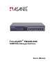
FriendlyNET® FM2008/2009 SNMP/Web Managed Switches User’s Manual
Quick Start Guide Follow these steps to install the switch: 1. Open the box and check the contents. See Chapter 1 for a complete list of the items included with the switch. 2. Install the switch in an equipment or wall rack, or prepare it for desktop placement. 3. Connect the power supply. 4. Connect network devices to the switch. 5. Refer to Chapters 4 and 5 for configuration and management capabilities.
FriendlyNET FM2008/2009 SNMP/Web Managed Switches User’s Manual Asanté Technologies, Inc. 821 Fox Lane San Jose, CA 95131 USA SALES 800-662-9686 Home/Office Solutions 800-303-9121 Enterprise Solutions 408-435-8388 sales@asante.com TECHNICAL SUPPORT 801-566-8991 Worldwide 801-566-3787 FAX www.asante.com support@asante.com Copyright © 2002 Asanté Technologies, Inc. Asanté and FriendlyNET are registered trademarks of Asanté Technologies, Inc. The Asanté logo is a trademark of Asanté Technologies, Inc.
Table of Contents Quick Start Guide ................................................................................................... 2 1. Introduction......................................................................................................... 5 2. Hardware Description......................................................................................... 9 3. Console Management ...................................................................................... 15 4. Web-Based Management.
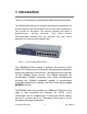
1. Introduction Thank you for purchasing the FM2008/2009 SNMP/Web Managed Switch. The FM2008/2009 switches are compact desktop-sized switches that are an ideal solution for the SOHO (Small Office or Home Office) network user. They provide full wire-speed, Fast Ethernet switching that allows a high-performance, low-cost connection. Each switch features store-and-forward switching and can auto-learn and store source addresses on an 8K-entry MAC address table. Figure 1-1.
With its built-in Web-based Management, managing and configuring the switch is easy: From cabinet management to port-level control and monitoring, the user can visually configure and manage the network via a web browser. Just click your mouse instead of typing command strings. However, the switch can also be managed via telnet, console, or SNMP management. Features • Conforms to IEEE 802.3, 802.3u, and 802.
• • • • • • IEEE 802.1ad Port Trunking LACP supported IEEE 802.
between the computer and the switch, while Telnet management is done over the network. Once the switch is on the network, use Telnet to log in and change the configuration. Note: The default IP address of the switch is 192.168.0.1. Both the default user name and the default password are root. Web Based Management The switch provides an embedded HTML web site residing in flash memory.
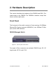
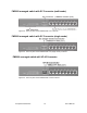
2. Hardware Description This section describes the hardware of the FM2008 and 2009. (The model shown is the FM2009. The FM2008 is identical, except that there is no fiber uplink port.) Front Panel The front panel of the switch consists of 8 auto-sensing 10/100Mbps Ethernet RJ-45 ports (automatic MDI/MDI-X), one 100Base-FX fiber port, and the LED indicators. FM2009 Managed Switch Figure 2-1.
FM2009 managed switch with SC Connector (multi-mode) Figure 2-2. The front panel of the FM2009 with a SC connector FM2009 managed switch with SC Connector (single-mode) Figure 2-3. The front panel of the FM2009 with a SC (single mode) connector FM2009 managed switch with VF-45 Connector Figure 2-4.
FM2009 managed switch with MT-RJ Connector Figure 2-5. The front panel of the FM2009 with a MT-RJ connector • RJ-45 Ports (Auto MDI/MDI-X): Eight 10/100Mbps auto-sensing for 10Base-T or 100Base-TX connections. ports; In general, MDI means connecting to another hub or switch while MDI-X means connecting to a workstation or PC. Therefore, Auto MDI/MDI-X means that the switch can connect to another switch or workstation without changing non-crossover or crossover cabling.
The following table provides descriptions of the LEDs statuses and meanings. These LEDs provide a real-time indication of systematic operation status.
Console Port: Switch management can be done through the console port. It requires a direct connection between the switch and an end station (PC) via an RS-232 cable. Desktop Installation Set the switch on a sufficiently large flat space with a power outlet nearby. The surface should be clean, smooth, level, and sturdy. Make sure there is enough clearance around the switch to allow attachment of cables, power cord and air circulation. Attaching Rubber Feet 1.
Important! Make sure the unit is supported until all of the mounting screws for each bracket are secured to the equipment rack. Failure to do so could cause the unit to fall, which may result in personal injury or damage to the unit. Equipment Rack Guidelines • • • Size: 10.0 x 5.2 x 1.5 inches Ventilation: Ensure that the rack is installed in a room in which the temperature remains below 40° C (104° F).
3. Console Management This chapter explains how to configure console management via a direct connection to the console port of the switch. Console management involves the administration of the switch via a direct connection to the RS-232 console port. This port is a female DB-9 connector. From the main menu of the console program, user has access to manage the functions of the switch. Connecting a Terminal or PC to the Console Port Figure 3-1.
Baud Rate: 9600 bps Data Bits: 8 Parity: none Stop Bit: 1 Control flow: None Figure 3-2. Communication parameters settings After entering the parameter settings, press the Enter key and the Login screen for console management appears. Console – Menu The switch provides a serial interface to manage and monitor the switch. The user can follow the Console Port Information provided by the web interface to use Windows HyperTerminal program to connect to the switch. Type the user name and password to login.
3.1 Main Menu To move through each screen’s menu, use the Tab key or Backspace bar to highlight an option, press Enter to select an option, and press the Spacebar to toggle between configuration options.
• Reboot Switch: Restarts the system or resets switch to default configuration • Logout: Exits the menu line program 3.2 Status and Counters From the main menu, select Status and Counters to configure the following: • Port Status • Port Counters • System Information 3.2.1 Port Status This page displays the current status of each port.
• Mode: Displays each port’s speed and duplex state • FlowCtrl: Displays the flow control status of each port; “On” indicates that flow control is enabled and “Off” indicates that it is disabled Actions-> Press the Tab or Backspace keys to choose action menu, and press the Enter key to select an option.
3.2.2 Port Counters This page displays the current counter statistics for each port. Actions-> Press the Tab or Backspace keys to choose action menu, and press the Enter key to select an option. : Exits the port status page, and returns to the previous menu : Sets all counters to 0 : Displays the previous page : Displays the next page 3.2.3 System Information This page displays the system information. Press the Esc key to return to the main menu.
• Hardware Version: Displays the hardware version • Default config value version: Displays the EEPROM version 3.3 Switch Static Configuration From the main menu, select Switch Static Configuration to configure the following options: • • • • • • • Administration Configuration Port/Trunk Configuration Port Mirroring Configuration VLAN Configuration Priority Configuration MAC Address Configuration Misc.
3.3.
3.3.1.1 Device Information This page displays the device information. Use the action menu line to change information. Actions-> : Allows the configuration of all items. When finished, press Esc to return to the action menu line. : Saves the new configuration. : Exits the Device Information page and returns to the previous menu. 3.3.1.2 IP Configuration From this page, the user can change the IP address from the default IP address. Use the action menu line to enter the new IP setting.
Actions-> : Configures all items. When finished, press Esc to go back to the action menu line. : Saves the new configuration. : Exits the IP Configuration page and returns to the previous menu. Note: You need to save and restart the computer after finishing IP configuration.
3.3.1.3 Change Username From this page the user can change the web management user name. 3.3.1.4 Change Password From this page the user can change the web management user password.
3.3.2 Port/Trunk Configuration From the Switch Static Configuration page, select Port/Trunk Configuration to change each port’s status and to configure trunking groups. Press the Space key to toggle between configuration options.
: Returns to the previous page. : Goes to the next page. 3.3.3 Port Mirroring Configuration From the Switch Static Configuration page, select Port Mirroring Configuration. Port mirroring is a method for monitoring traffic in switched networks. Traffic through all the ports can be monitored by one specific port.
: Configures all items. When finished, press Esc to go back to the action menu line. : Saves the new configurations. : Returns to the previous page. : Goes to the next page. 3.3.4 VLAN Configuration From the Switch Static Configuration page, select the VLAN Configuration option to configure the following: • VLAN Configure • Create a VLAN Group • Edit/Delete a VLAN Group 3.3.4.1 VLAN Configure Use the console connection to enable VLANs on the switch.
• PVID (Port VID): Set the port VLAN ID that will be assigned to untagged traffic on a given port. This feature is useful for accommodating devices that you want to participate in the VLAN but don’t support tagging. Only one untagged VLAN is allowed per port • Ingress Filter 1: Matches Ingress Filtering Rule 1. If enabled, drops any frame received by the port whose tag doesn’t match the port’s configured VID.
• Member: Press the Space key to toggle each port’s VLAN membership. There are three options: UnTagged: the member port is untagged port Tagged: the member port is tagged port No: the port is not a member of the VLAN group Actions-> : Exits this page and returns to the previous menu. : Configures all items. When finished, press Esc to go back to the action menu line. : Saves the new configurations. : Returns to the previous page. : Goes to the next page. 3.3.4.
then press Enter. 3. Modify the options as desired, or add or remove member ports as desired. 4. After completing the desired changes to the VLAN, press to save the new configuration. Note: The default VLAN cannot be deleted, nor can the VLAN Name or VLAN ID be modified.
3.3.5 Priority Configuration There are 7 priority levels that map traffic to two queues. The High/Low Queue Service Ratio (H:L) allows the user to select the ratio of high priority packets to low priority packets processed by the switch. First In First Out: The packets are sent out in the order they were received. High to Low: High priority packets are sent before low priority packets. Ratio: The user may select the precedence given to packets in the switch's high-priority queue.
Actions-> : Configure all items. When finished, press Esc to go back to the action menu line. : Saves the new configurations. : Exits this page and returns to the previous menu. 3.3.6 MAC Address Configuration 3.3.6.1 Static MAC Address When you add a static MAC address, it remains in the switch's address table, regardless of whether the device is physically connected to the switch.
Add static MAC address 1. Press --> key to add a static MAC address. 2. Enter the MAC address of a device from which the port should permanently forward traffic regardless of the device’s network activity. Enter the address without separators (e.g. 000094abcdef) 3. In the Port num item, enter the port number. 4. If tag-based (802.1Q) VLANs are set up on the switch, static addresses are associated with individual VLANs. Type the VLAN ID number associated with the device’s MAC address. 5.
Delete static MAC address 1. Press the key to delete a static MAC address. 2. Choose the MAC address that you want to delete and then press Enter. 3. After deleting the static MAC address, press to have the changes take effect.
3.3.6.2 Filter MAC Address From this screen, add, edit, or delete filter MAC addresses. 3.3.7 Miscellaneous Configuration 3.3.7.1 Port Security By default, the port security feature is disabled for each port to allow for address learning. When port security is enabled, the port will only accept incoming packets from a known static MAC address. The user can enable port security on a port, and then use the Static MAC Address page to define a list of MAC addresses that can use the secure port.
Select to enable or disable the port security. Press the Space bar to toggle between enabled and disabled on each port. Press Esc to go back to the action menu line, and then select to save the new configuration. 3.3.7.2 MAC Age Interval From this screen, you may enter the time (in seconds) that an inactive MAC address remains in the switch’s address table. The valid range is 300–765 seconds. The default is 300 seconds.
Actions-> : Configure all items. When finished, press Esc to go back to the action menu line. : Saves the new configurations. : Exits this page and returns to the previous menu. 3.3.7.3 Broadcast Storm Filtering From this page you may configure the broadcast storm filter. Press to proceed to configure the broadcast storm filter. Press the Spacebar to choose the threshold value. This is the percentage of total traffic that may be broadcast before the filter takes effect.
3.3.7.4 Max bridge transmit delay bound • Max bridge transmit delay bound: Limits the packet queue time in the switch. If enabled, the packets will be dropped from the queue after the time has expired. Press the Space bar to set the time. The options are 1 second, 2 seconds, 4 seconds and off. The default is 1 second • Enable Delay Bound: Limits the low priority packets’ queuing time in the switch. If enabled, the low priority packets that stay in the switch past the Max Delay Time will be sent.
Actions-> : Configure all items. When finished, press Esc to go back to the action menu line. : Saves the new configurations. : Exits this page and returns to the previous menu. 3.4 Protocol Related Configuration 3.4.1 Spanning Tree Protocol (STP) 3.4.1.1 STP Enable On this screen you may enable or disable the Spanning Tree function. Press the Space bar to toggle between Enable and Disable.
3.4.1.2 System Configuration On the left of this screen, you can view the Root Bridge Information. On the right, you can configure new values for the STP parameters. Bridge Priority Setting the Bridge Priority to a low value will increase the likelihood that the current bridge will become the root bridge. If the current bridge is located physically near the center of your network, you may wish to decrease the Bridge Priority from its default value of 32768 to make it become the root bridge.
occurred, and it begins recalculating the spanning tree. The default setting for Maximum Age is 15 seconds. Forward Delay After a recalculation of the spanning tree, the Forward Delay parameter regulates the delay before each port begins transmitting traffic. If a port begins forwarding traffic too soon (before a new root bridge has been selected), the network can be adversely affected. The default value for Forward Delay is 5 seconds.
3.4.1.3 Per-port Configuration PortState: View the spanning tree status for each port. PathCost: Port path cost is the spanning tree parameter that assigns a cost factor to each port. The lower the assigned port path cost is, the more likely that port will be accessed. The default port path cost for a 10Mbps or 100Mbps port is the result to the equation: Path cost = 1000/LAN speed (in Mbps) Therefore, for ports operating at 10Mbps, the default port path cost is 100.
3.4.2 SNMP Use this page to define management stations as trap managers and to enter SNMP community strings. You can also define a system name, location, and contact person for the switch. 4.4.2.1 System Options Select to enter the information, and then select to have the changes take effect.
System Name: Enter a name to be used for the switch. System Contact: Enter the name of contact person or organization. System Location: Enter the location of the switch. 3.4.2.2 Community Strings Use this page to enter SNMP community strings. Community Name: Enter the name of the current string. Write Access: Designate the access rights of the current string.
Actions-> : Creates community strings. : Modifies items. When finished, press Esc to go back to the action menu line. : Deletes a community string. Press to have your changes take effect. : Saves the new configurations. : Exits this page and returns to the previous menu. 3.4.2.3 Trap Managers A trap manager is a management station that receives traps, the system alerts generated by the switch. If no trap manager is defined, no traps are issued.
Actions-> : Creates a trap manager. : Modifies all items. When finished, press Esc to go back to the action menu line. : Deletes a trap manager. Press to have your changes take effect. : Saves all the new configurations. : Exits this page and returns to the previous menu.
3.4.3 GVRP On this page you can enable or disable the GVRP (GARP VLAN Registration Protocol) support. Press the Space bar to toggle between Enabled/Disabled. Actions-> : Configure all items. When finished, press Esc to go back to the action menu line. : Saves all new configurations. : Exits this page and returns to the previous menu.
3.4.4 Link Aggregation Control Protocol (LACP) 3.4.4.1 Aggregator Setting Group: Displays the trunk group ID. LACP: Press the Space bar to enable or disable LACP (Link Aggregation Control Protocol) support. If enabled, the group is a LACP static trunking group. If disabled, the group is a local static trunking group. LACP Work Port Num: The maximum number of ports that can be aggregated at the same time.
Actions-> : Configure all items. When finished, press Esc to go back to the action menu line. : Saves all configurations. : Exits this page and returns to the previous menu. 3.4.4.2 State Activity Active: The port automatically sends LACP protocol packets. Passive: The port does not automatically send LACP protocol packets, but responds only if it receives LACP protocol packets from another device.
Actions-> : Configure all items. When finished, press Esc to go back to the action menu line. : Saves all configurations. : Exits this page and returns to the previous menu. 3.4.4.3 LACP Status In this page, you may view the trunking group information. Actions-> : Exits this page and returns to the previous menu. : Returns to the previous page. : Goes to the next page.
3.5 Reboot Switch Default: Resets the switch to the default configuration. Restart: Reboots the switch. 3.6 Xmodem Upgrade You can load an image file via an Xmodem upgrade during a system restart. Follow the steps below to perform an Xmodem upgrade via the console port. 1. Press the X key to start upgrading for Xmodem. 2. Disconnect the terminal and modify the baud rate to 57600bps, then reconnect to the terminal.
3. Select send file under the transfer menu from the menu bar. 4. Press the Browse button to select the path to the new image file. 5. Select 1K XModem protocol and press Send button. 6. After successfully upgrading the new firmware, please modify the baud rate setting of your terminal program to 9600bps.
FriendlyNET FM2008/2009 54 User’s Manual
4. Web-Based Management This section introduces the configuration and functions of the web-based management of the switch. The FM2009 provides an embedded HTML website residing in flash memory that allows users to manage the switch from anywhere on the network using a standard web browser. Note: For those who use Windows 2000 and have installed Service Pack#2, the web management function may have display problems if the IE version is 5.5 or older. Web Management Function 1.
4.1 Home Page After entering the user name and password, you will come to the Home page, as shown below.
4.
4.3 Port Statistics The Port Statistics page provides the current status of the unit. 4.4 Administrator The management functions include: IP Address, Switch Settings, Console Port Information, Port Controls, Link Aggregation, Filter Database, VLAN Configuration, Spanning Tree, Port Mirror, SNMP, Security Manager, TFTP Update Firmware, Configuration Backup, Reset System and Reboot. 4.4.1 IP Address From this page, you can change the IP Address from the default value (recommended).
4.4.2 Switch Settings 4.4.2.1 Basic The Basic Switch Settings page displays the current information of the switch.
4.4.2.2 Advanced From the Switch Settings page, click the Advanced button to display or configure the following information: • MAC Address Age-out Time: Enter the number of seconds that an inactive MAC address can remain in the switch's address table. The valid range is 300–765 seconds, the default is 300 seconds • Max bridge transit delay bound control: Limits the packets’ queuing time in switch. If enabled, the packets in the queue will be dropped when the time expires.
Priority Queue Service settings: • First Come First Served: The sequence of packets sent depends on their order of arrival • All High before Low: All high priority packets are sent before any low priority packets • Weighted Round Robin (WRR): Select the preference given to packets in the switch's high-priority queue. These options represent the number of high priority packets sent before one low priority packet is sent.
Protocol Enable Settings: • Enable Spanning Tree Protocol: Enabled by default (recommended) • Enable Internet Group Multicast Protocol: IGMP protocol enabled by default • VLAN Operation Mode: Select Port Based, 802.1Q without GVRP, 802.
GVRP (GARP [Generic Attribute Registration Protocol] VLAN Registration Protocol) GVRP allows automatic VLAN configuration between the switch and nodes. If the switch is connected to a device with GVRP enabled, you can send a GVRP request using the VID of a VLAN defined on the switch; the switch will automatically add that device to the existing VLAN. 4.4.3 Console Port Information The console is a standard UART interface used to communicate with the serial port.
4.4.4 Port Controls From this page you can configure the following parameters: • State: Disable or enable each port • Auto Negotiation: Disable or enable auto negotiation for each port • Speed: Set port speed (100Mbps or 10Mbps) on ports 1-8; port 9 is 100Mbps only • Duplex: Set full-duplex or half-duplex mode for each port • Flow Control: Enable or disable flow control for each port 4.4.5 Trunking Trunking provides a standardized means for exchanging information between multiple devices on a link.
4.4.5.1 Aggregator setting 1. System Priority: A value used to identify the active LACP. The switch with the lowest value has the highest priority and is selected as the active LACP. 2. Group ID: To create an aggregated link across two or more ports, choose the "Group ID" and click Get. 3. LACP: If enabled, the selected group becomes an LACP static trunking group. If disabled, the selected group becomes a local static trunking group. All ports support LACP dynamic trunking groups.
5. Select the ports to join the trunking group 6. If LACP is enabled, you can configure the LACP Active/Passive status on each port. 7. Click Apply. 4.4.5.2 Aggregator Information When setting the LACP aggregator, you can view the related information by clicking Aggregator Information. 4.4.5.3 State Activity Click on State Activity to configure each port to automatically send LACP protocol packets.
A link that has two passive LACP ports will not perform dynamic LACP trunking because both ports are waiting for a LACP protocol packet from the opposite device. If you select active LACP, the active status will be created automatically when you select the trunking port. 4.4.6 Filter Database 4.4.6.1 IGMP Snooping The switch supports IP multicasting.
multicast addresses range from 224.0.0.0 through 239.255.255.255. The Internet Group Management Protocol (IGMP) is an internal protocol of the Internet Protocol (IP) suite. IP manages multicast traffic by using switches, routers, and hosts that support IGMP. Enabling IGMP allows the ports to detect IGMP queries and report packets and manage IP multicast traffic through the switch.
connected to the switch. This saves the switch from having to re-learn a device's MAC address when the device is active on the network again. To add a static MAC address: 1. From the main menu, click Administrator, and then click Filter Database. 2. Click Static MAC Addresses. In the MAC address box, enter the MAC address to and from which the port should permanently forward traffic, regardless of the network activity of the device. 3. In the Port Number box, select a port number. 4. If tag-based (IEEE 802.
4.4.6.4 MAC Address Filtering MAC address filtering allows the switch to drop unwanted traffic. Traffic is filtered based on the source or destination addresses. For example, if your network is congested because of high utilization from one MAC address, you can filter all traffic transmitted from that MAC address, restoring network flow while you troubleshoot the problem. To add a MAC address filter 1. From the main menu, click Administrator, then click Filtering Database.
2. Click MAC Filtering. 3. Click Add. 4. In the MAC Address box, type the MAC address (without hyphens) to filter. 5. Select the port that will filter traffic from this address. 6. If port-based or tag-based VLANs are configured on the switch, type the name or VID of the VLAN to use the filter. 7. Click Apply. 4.4.7 VLAN configuration A Virtual LAN (VLAN) is a logical network grouping that limits the broadcast domain.
Protocol-based VLANs In order for an end station to send packets to different VLANs, it itself has to be capable of tagging packets it sends with VLAN tags, or it must be attached to a VLAN-aware bridge that is capable of classifying and tagging the packets with different VLAN IDs, based on not only on the default PVID but also other information about the packet, such as the protocol. 4.4.7.1 Basic Create a VLAN and add tagged member ports to it. 1.
4.4.7.2 Port VID Configure port VID settings From the main Tag-based (IEEE 802.1Q) VLAN page, click Port VID Settings. Port VID (PVID) From this page, you can set the Port VLAN ID that will be assigned to untagged traffic on a given port. For example, if port 9's Default PVID is 100, all untagged packets on port 9 will belong to VLAN 100. The default setting for all ports is VID 1. This feature is useful for accommodating devices that you want to participate in the VLAN but that don't support tagging.
Ingress Filtering Ingress filtering lets frames belonging to a specific VLAN to be forwarded if the port belongs to that VLAN. The switch has two ingress filtering rules, as follows: Ingress Filtering Rule 1: Forward only packets with a VID matching this port's configured VID. Ingress Filtering Rule 2: Drop untagged Frames. 4.4.8 Spanning Tree The Spanning Tree Protocol (STP) is a standardized method (IEEE 802.1D) for avoiding loops in switched networks.
1. You can view Spanning Tree information about the Root Bridge, as in the following screen: 2. You can view Spanning Tree port status, as in the following screen: 3. You can configure new values for the STP parameters, and then click the Apply button to modify.
Parameter Description You can change the priority value used to identify the root bridge. The Priority bridge with the lowest value has the highest priority and is selected as the root. Enter a number 1 through 65535. You can change the Max Age value, the number of seconds a bridge Max Age waits without receiving Spanning Tree Protocol configuration messages before attempting a reconfiguration. Enter a number 6 through 40.
4.4.9 Port Mirroring The Port Mirror is a method for monitoring traffic in switched networks. Traffic through the ports can be monitored by one specific port. That is, traffic that goes into or out of the monitored ports will be duplicated into the analysis port. Port Mirroring State: Enable or disable the port mirror function. Analysis Port: Select which port will copy all monitored ports’ traffic. Mirror Ports: The ports you want to monitor.
Use this page to define management stations as trap managers and to enter SNMP community strings. You can also define a name, location, and contact person for the switch. Fill in the system options data, and then click Apply to update the changes on this page. 4.4.10.1 System Options • Name: Enter a name to be used for the switch • Location: Enter the location of the switch • Contact: Enter the name of a person or organization 4.4.10.
4.4.10.3 Trap Manager A trap manager is a management station that receives traps, the system alerts generated by the switch. If no trap manager is defined, no traps are issued. Create a trap manager by entering the IP address of the station and a community string. 4.4.11 Security Manager Use this page to change the web management user name and password. Default User name: root Default Password: root 4.5 TFTP Update Firmware TFTP is the Trivial File Transfer Protocol.
4.6 Configuration Backup 4.6.1 TFTP Restore Configuration Use this page to set TFTP server address. You can restore the EEPROM value from here, but you must put the back image in TFTP server, the switch will download the back flash image. 4.6.2 TFTP Backup Configuration Use this page to set the TFTP server IP address. You can save the current EEPROM value from here, then go to the TFTP restore configuration page to restore the EEPROM value.
4.7 Reset System Reset the switch to the default configuration. 4.8 Reboot Reboot the switch in software reset.
5. Technical Specifications Standards Compliance IEEE 802.3 10Base-T Ethernet, Protocol CSMA/CD IEEE 802.3u 100Base-TX/FX Fast Ethernet Max Forwarding and 14,880 pps per Ethernet port Max Filtering Rate 148,800 pps per Fast Ethernet port LED Indicators Per Port: (10/100 UTP): 100Mbps, Link/Activity, Full Duplex (3 LEDs) Fiber Port (FM2009 only): 100Mbps, Link/Activity, Full Duplex (3 LEDs) Per Unit: Power Copper Network Cables 10Base-T: 2-pair UTP/STP Cat.
6. Troubleshooting This section is intended to help you solve the most common problems with installation of the FM2008/2009 switch. Incorrect connections Faulty or loose cables Look for loose or obviously faulty connections. If they appear to be OK, make sure the connections are snug. If that does not correct the problem, try a different cable.
Diagnosing LED Indicators The switch can be easily monitored through LED indicators, which assist in identifying common problems that you may encounter. If the power LED indicator does not turn on when the power cord is plugged in, you may have a problem with the power outlet or with the power cord. However, if the switch powers off after having been running for a while, check for loose power connections, power losses, or surges at the power outlet.
FriendlyNET 2-Year Limited Warranty Subject to the following limitations and exclusions, Asanté warrants to the original end user purchaser that the covered products will be free from defects in title, materials, and manufacturing workmanship for a period of two years from the date of purchase. This warranty excludes fans, power supplies, non-integrated software, and accessories.
MERCHANTABILITY OR FITNESS FOR A PARTICULAR PURPOSE ARE HEREBY DISCLAIMED. ASANTÉ'S LIABILITY ARISING FROM OR RELATING TO THE PURCHASE, USE OR INABILITY TO USE THE PRODUCTS IS LIMITED TO A REFUND OF THE PURCHASE PRICE PAID.