
Service Manual, Parts List, Diagrams and Assembling Charts
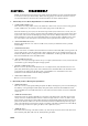
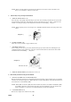
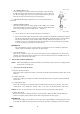
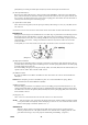
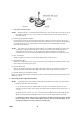
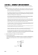
Table Of Contents

CHAPTER I. DISASSEMBLY
NOTE: As red lacquered spots are the spots securely fixed after making necessary technical adjustment,
do not unscrew such spots unnecessarily. When removing springs, care must be exercised so as not to
give any deformation to the springs; also refrain from taking out springs with bare fingers.
1. Disassembly of Cover Plates, Rapid Wind Lever and Rewind Knob.
a. RAPID WIND LEVER (C03)
Take out the arrow ring retainer screw (C54). When the counter screw (C36) is removed, using special
tool No. 225K-C36-A, the counter (C12) and counter spring (C60) can be taken out.
When the actuator lug screw (C53) for the advance lug actuator (C07) is taken out, 2 screws (C73) for
(C03) can be removed. As (C03) is securely fixed with a binding agent to the upper surface of the wind-
up lever seat (C35), dissolve the binding agent, using such solvent as Methyl-ethyl-ketone or Acetone,
before attempting to remove the screw. Remember that in our current products a binding agent is used
not on the surface of the wind-up lever seat (C35) but on the rapid wind lever retainer screw (C73).
b. SHUTTER SPEED DIAL (E23)
With the shutter dial set at " B," remove 3 small screws (23) and you will find it easier to perform
disassembling.
c. REWIND KNOB (D06)
With a screw driver or a similar tool inserted into the fork of the rewind shaft (D05), which goes into one
end of a film cassette, rotate the crank (D10) counter-clockwise more or less forcibly and unscrew it. If
the flat nut (D09) is taken out, using special tool No. 225K-D09-A, the film type dial washer (D02) and
film type dial (D08) will come out simultaneously.
d. TOP COVER PLATE (A03)
Take out 1 screw (18) on the upper side of the top cover plate (A03) and then 2 screws (19) on both sides
of the finder eye-piece and push the plate strongly upward.
e. FRONT COVER PLATE (A05)
Remove 4 screws (19) and you will find the front cover adjust washer (A39) between the front cover
plate (A05) and the body proper (A01); this is intended for the mechanical back to be 45.46mm. In the
event (A05) is not replaced, fix the plate at time of reassembling to its original place, and correct
dimensions can be maintained without making adjustment.
f. BOTTOM COVER (A04)
Remove 2 screws each (18) and (16).
2. Disassembly of Mirror Housing and Optical Parts.
a. PRISM SEAT (B01)
Take out 3 screws (13) by tightly holding the prism seat (B01) with fingers to protect it from floating by
the elasticity of the ground glass holder (B79). The prism (AF17) should not be dismantled from the
prism seat (B0l) as far as possible, but when it is to be removed, unscrew either one of the 2 adjustment
screws (21).
b. MIRROR HOUSING (B02)
Unloose the screw (I) of the lug plate (B77) at X contact on the bottom part of the body proper (A0l),
slowly correct the cord B (B73) with tweezers to make it straight, remove 2 screws (11) and 2 screws
(B71) and take out the mirror housing (B02) slopewise frontward. While taking the mirror housing out,
push it in the direction of B02 so as not to let the curtain actuator lever IB20I hook up the body proper
(A01). Care must also be exercised not to let the cut opening of the mirror actuator lever, bottom (B19),
hook up the edge of either the coupler gear (E18) or the coupler lever (C15).
c. MIRROR (AF12)
Press inward the front edge of the mirror (AF12), say, with the tip of tweezers, and 2 front claws of the
mirror retainer plate (B12) will come off, thereby floating the mirror.
230-2 -5-