PRODU CT N O.
TABLE OF CONTENTS Page INTRODUCTION.....................……………………………............................................................... 4 SUMMARY OF STRUCTURE AND PERFORMANCE ......……………………….....................… 4 CHAPTER I. DISASSEMBLY......................................…………………………...................... 8 1. Disassembly of Cover Plates, Rapid Wind Lever and Rewind knob..................................... 8 a. Rapid Wind Lever (C03) b. Shutter Speed Dial (E23) c. Rewind Knob (D06) d. Top Cover Plate (A03) e.
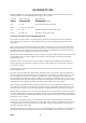
I N T RODU CT I ON This Service Manual is prepared for servicing Product # 230 2; however, since the following products have structures similar to 230 2. This Manual will also apply to these products: Product # Model Description Major Difference 229-2 S1. H1. S2. H2 Semi-automatic diaphragm. 230 S3. H3 Old-type fully automatic diaphragm. 229-3 S1. H1. S2. SB. SB2 232 SV. H3v Self-timer, automatic re-setting film counter. 230-3 Sla. Hla, S2 Automatic re-setting film counter.
exposure timing, the time required will be that much prolonged. For facilitating better understanding of this Manual as well as for convenience of the reader when making requisition for interchangeable parts and/or tools, lists and diagrams are attached herewith as Attachments. Explanations with respect to disassembly are given in the order of work to be performed, while those pertaining to assembly are described in the order opposite to the work of disassembly.
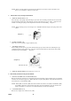
CH APT ER I . DI SASSEM BLY NOTE: As red lacquered spots are the spots securely fixed after making necessary technical adjustment, do not unscrew such spots unnecessarily. When removing springs, care must be exercised so as not to give any deformation to the springs; also refrain from taking out springs with bare fingers. 1. Disassembly of Cover Plates, Rapid Wind Lever and Rewind Knob. a. RAPID WIND LEVER (C03) Take out the arrow ring retainer screw (C54).
NOTE: Never touch the surface of the mirror with a fingertip or any kind of tool. If the mirror gets dusty, use a soft brush or a blower to dust it off. 3. Disassembly of Top Transport Mechanism. a.
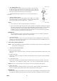
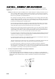
c. "R" LEVER PARTS (C70) As the "R" button is screwed in, remove it by turning it counter-clockwise forcibly with finger. When the "R" lever retainer screw (C52) is taken out, the "R” lever spring (C62), "R” lever (C70), W9 and bottom 1st gear (C25) will come out from the lower bottom 1st gear shaft (C46). d. PIN ADJUST PLATE (C17) Remove the screw (14) and then unloose 2 screws (23). e. WIND UP SHAFT PARTS Press the top main gear (C23), using special tool No.
plate (E05) by loosening the release plate nut (E119), and the desired parts can be taken out. (5) Slow Speed Rod (F12) Ease the cam coupler plate nut (F11), using special tool No.225K-FII-A, remove the cam coupler plate (F02). Then remove LW13, intended to check up-and-down movement of the slow speed rod (F12), and the governor at the bottom of the body proper and its coupling parts can be taken out at the same time in one body from the bottom parts of the body proper.
Diagram 5 b. SHUTTER CURTAIN PARTS NOTE: When attempting to overhaul the shutter curtain parts, strict care must be exercised not to tear off the curtain from the pipes; not to make a hole in the curtain with such tool as tweezers; and not to stain them with oil.
CH APT ER I I . ASSEM BLY AN D ADJ U ST M EN T In this Chapter II, photographs are shown, besides diagrams, in the order of assembling, where considered helpful. For instance, photo No. 3 shown under 1. b, illustrates the assembled condition up to the stage of the stopper (C11). NOTE:Disassembled parts, before assembling, need a careful washing and or dusting with either a piece of cloth or a blower.
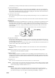
Photo 1 (2) Relative position of the shutter curtains and the bottom selector gear (E14), after assembling (E14) with bulb lever parts, should be determined by gearing (El4) with (Ell) in the wound-up condition of the shutter curtain as illustrated in Diagram 7. (E14) and the pinion shaft need oiling. NOTE: When resetting the shutter curtains to the un-cocked condition, do it slowly.
Diagram 8 Location must be adjusted the tolerance of 0.5mm b. STOPPER (C11) After installing the 1st curtain checker arm (E07) and the stopper (C11), the gap between the projected point of the selector gear stopper (E77) and (C11) should be adjusted to be 0.2-0.3 mm in the cocked condition. This adjustment should be made by turning the screw (22) which is screwed in through the back of (A01). (Diagram 9) Diagram 9 Photo 3 c.
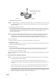
Ease the force of (C75) and also the pressure on (E08), and the top main gear (C23), (E16) (EOS) slightly turn backward with the tension of the wind-up shaft spring (C57); then the non-return arm (C04) springs into the groove underneath (E16) and then stops. While maintaining this position, fix the top idling gear (E17), paying careful attention to "t". (Diagram 11) Diagram 11 Then putting on the spill receptacle plate (E09) and screw in with the idling gear retainer screw (E50).
Photo 4 REFERENCE: How to make adjustment if the pin adjust plate (C 17) is of the old type: In the case of (C17) of the old type (prior to the introduction of the improved one), the range of adjusting the position of the coupler lever pin (C51), after completion of the adjustment of the idling gear, is slight; and accordingly, (E16) should be fixed along the groove of (E20), after correctly positioning (C51) by turning (C75).
In the event a wide gap has been created on either parts, lift the top 1st gear (C20) and change its engaging position with that of (C21). In the event any one of the gears on the upper part of the body proper has been replaced, proper adjustment of the aforementioned gap may sometimes be found impossible. In such a case as this where a delicate adjustment is called for, 5 kinds of the lever seat lug (C05), each different in length, are available.
f. PINION COUPLER LEVER (E10) AND COUPLER LEVER (C15).
(1) Adjustment of curtain travel speed. (2) Adjustment of high speed exposure timing (l/1000 sec-1/30 sec.). (3) Adjustment of slow speed exposure timing (1/15sec.- 1 sec.) a. CURTAIN SPEED The curtain travel speed is the time required for the shutter curtains to run through the picture format (36 mm). In this model, the speed is adjusted to be 16.5 +/- 0.3 ms under the ambient temperature of approx. 20o C. The adjustment has to be performed in the following order: (1) Set the speed dial (23) at 1/1000.
d. SLOW SPEED EXPOSURE TIMING Slow speed exposure timing can be determined by adjusting the exposure timing for 1/15 sec (6.7 ms), and the exposure timing for the rest (1/8-1 sec) may be determined automatically by dint of the slow speed cam (F01). Better stability of the exposure timing can be expected if the timing for 1/15 sec is adjusted so as to be very slightly prolonged, viz., 7-8 ms.
Diagram 19 f. EXPOSURE TIMING AT VARIOUS POINTS ON THE PICTURE FORMAT. In a camera with focal plane shutter, the slit formed by its shutter curtains travels right in front of the picture format, thereby providing exposure on the film successively. In view of this, it becomes necessary to measure the time of exposure at various points on the picture formal. In this camera, the adjustment of the above exposure timing should be made at 1/1000 sec. If the travel time of the shutter curtains at 1/1000 sec.
uncocked, (C07) should not idle in the direction of its rotation, checked by the cut-opening of (A03), and (C53). (Diagram 22, 23) Diagram 22 Diagram 23 If the gap of (C07) is considerable, it will invariably result in the counter dial travelling double scale space even by single cocking. In this event, it is necessary to minimize the gap by hammering out the "A" part of (C07). When (C53) can not be installed, file off !he "A" part.
but if moved more than 1 1/3 pitch, the "B" part must be filed off properly. Diagram 27 Lastly, install the counter plate (C12) joined with (C28), namely, (0C12) and then match the index mark of the covering ring (C39). The index mark should be matched before cocking. (Diagram 28) Diagram 28 4. Adjustment of X Contact. X contact should be so adjusted as to close at the moment the 1st shutter curtain has run through the picture format.
Diagram 30 6. Adjustment of Mechanical Hack. The distance from the film guide rails to the helicoid seat (A15) affixed to the front cover (A05) is referred to as " Mechanical Back," which should be adjusted to be 45.46 +/- 0.03 mm. Use the special gauges and tools illustrated in Attachment 1, viz., 230N-A01-A, dial gauge, dial comparator, 230N A15 A and 230NA01-A2. First, on the dial comparator, place the special gauge 230N-A01-A to be followed by 230N A01 A2, and adjust the dial gauge to zero.
Diagram 33 Diagram 34 Adjustment should be made so that the image at the center as well as at the four corners on the ground glass are equally in focus. NOTE: (1) Three pcs of screw (B63) have to be turned very slowly and alternatively. (2) Upon completion of the adjustment, securely affix (B63) with binding agent.
CH APT ER I I I . FI N AL T EST S Upon completion of all assemblies, final tests should be performed. Needless to say, such strict, thoroughgoing tests as are performed at the time of manufacture are not only practicable but unnecessary. However, final tests should be conducted according to the following procedures. Inasmuch as each of the following paragraphs has much to do with what are described in Chapter II, refer as far as possible to applicable paragraphs in Chapter II.
Measure the time of exposure at 1/1000 sec, and check whether the exposure is consistent. Also find out if there is any even-lessness if viewed from the rear. Then measure the time of exposure at 1/15 sec. The best way of checking the shutter bounce is to carefully watch from the back side of the picture format, releasing the shutter at 1/60 sec. by holding and directing the camera toward a bright background, say, white walls or the sky. Check the exposure time at 1 sec.
CH APT ER I V . CAU SES OF DEFECT S AN D SERV I CI N G DEFECTS Rapid wind lever stops while cocking, or does not return automatically. CAUSES Damaged spring (C19) SERVICING Replace (C19) 1. When the shutter is released, the spill (E08) remains lowered. How to determine: Turn the sprocket hard in the rewinding direction. If the spill position is proper, the sprocket turns a little. If the spill remains lowered, the sprocket does not rotate at all. a.
DEFECTS CAUSES SERVICING Film counter dial does not move. 1. The gap between the extreme point of 1. Adjust the engaging position of (C28). the counter advance lug (C06) and the (Refer to Chapter II, 3.) tooth of the transport gear (C28) is wider than the specified 1/3 pitch. 2. Damaged (C06). 2. (0C07) is to be replaced. This happens especially when the wind-up lever is returned too rapidly. Film counter dial indicator jumps 2 notches with single cocking: 1. The gap between the extreme point of 1.
DEFECTS CAUSES SERVICING Shutter curtains do not start. Though the mirror seat (B10) flips up, the 1st curtain checker arm (E07) does not slip off the stud of the top selector gear (E15). Check if the mirror seat flipping mechanism is functioning smoothly. If found O.K., replace the mirror seat spring (B44) as it might have been weakened. Slow speed shutter exposure timing is too fast. Relative position of the slow speed lever Make necessary adjustment.
LI ST OF SPECI AL SERV I CE T OOLS 225K C36-A C36 Driver 230N-A01-A Mechanical Back Gauge 226K-D15-A D15 Driver Dial Gauge Mechanical Back Gauge 225K-D09-A D09 Driver Dial Comparator Mechanical Back Gauge 225-C23-A C24 Holder 230N-A15-A Mechanical Back Gauge 230N-A01-A2 Mechanical Back Gauge 225K-C24-A C24 Driver 229K-E64 65-A Shutter Curtain Wind-Up Driver 225K-E48-A E87 Adjust Driver 230K-E76 A E85 Driver 230-2 -29-
Watch Oiler 225K-F11-A F11 Driver 230K B63 A B63 Adjust Driver Oil Cup 230K-E69-A E85 Holder 230-2 -30-
LIST OF LUBE OIL 1. “L” Lubrication. The letter "L" stands for liquid lubrication oil. In the event a watch-oiler is used, "one droplet of oil" means such quantity of oil as is found on the extreme point of the watch-oiler when it is lined from the oil cup after soaking into oil at a 45o angle. When the extreme point of the oiler is placed on the contact point of the parts to be oiled, oil will be absorbed in the contact point because of the capillarity of oil.
L-l Quantity of Oil Where To Apply. (Number indicates droplets of watch oiler) Between (E31) (1st curtain pinion shaft) and shaft bearing of (C01) (top mec. plate). Between ( E31) (1st curtain pinion shaft) and shaft bearing of (C02) (bottom mec. plate) Between (E32) (2nd curtain pinion shaft) and shaft bearing of (C 01) (top mec. plate). Between (E32) (2nd curtain pinion shaft) and shaft bearing of (C02) (bottom mec. plate). Between (E18) (coupler gear) hole and (E53) (Coupler gear retainer screw).
G1 Between (B35) (mirror actuator lever shaft), (B18) (mirror actuator lever, top) and (B19) (mirror actuator lever, bottom) hole Contact between (B42) (mirror seat lug stud) and (B83) (mirror checker spring). Thin Japanese writing brush. Between (C24) (bottom main gear) and shaft bearing of (C02) (bottom mec. plate). Thin Japanese writing brush. Between groove of (C24) (bottom main gear) and (C58) (take-up spool spring), (W17) and (C14) (bottom take-up spool brim).
Between narrow part of (C3D) (sprocket shaft) and hole of (A01) (body proper). " (small quantity) Between (C30) (sprocket shaft), hole of (C02) (bottom mec. plate) and (W22). " (small quantity) Between (C31) (wind up shaft) and (C57) (wind up shaft spring). Thin Japanese writing brush. Contact between (C32) (wind up shaft bearing; and (C23) (top main gear). " Between (C41) (top 2nd gear column) and hole of (C21) (top 2nd gear).
LIST OF BONDS NOTE: 1. Immediately after use of binding agent, its container has to be capped tightly. Preferably it should be divided and kept in as smaller containers as possible. When not in use, the container has to be capped tightly. 2. Do not use stale binding agent that has been kept for a long time. The binding strength deteriorates if thinned from time to time with solvents.
Penguin No. 332 N Binding Places Tool B26 (sync. seat insulator) B25 (sync. seat) Spatula E64 (1st curtain shutter) E35 (1st curtain wind shaft, top) E64 " E64 " E36 (1st curtain wind shaft, bottom) " E65 (2nd curtain shutter) E 39 (2nd curtain pipe) Brush E111 (X contact pin) Thin Japanese writing brush Thin stick Penguin No. 251 E115 (insulator tube) Red Lacquer E87 (bulb lever adjust nut) E06R (bottom bulb lever), set screw, flat 1.4x2.
EX PLODED I LLU ST RAT I ON S Fig.
Fig.
Fig.
Fig.
Fig.
Fig.
LI ST OF SERV I CE PART S Produc t N o. 2 3 0 -2 ASAH I PEN T AX S3 Note: The parts with numbers starting with ' 0' are assembled parts, and the *marked parts are included in the ' 0 '-starting assembled parts. PART NO. DESCRIPTION 0A01 Body proper assembly (A01, E118) 1 0A02 1 0A03 Back cover assembly (A02, A09, A10, A13, AI4, A25, A27, A32.
A33 * Back cover covering 1 A34 * Cassette holder rivet 2 A35 * Earth 1 A36 * Pressure plate retainer stud B 2 A37 * Hinge rivet 3 A39 Front cover adjust washer 4 A40 * Indicator window 1 A41 Light seal 2 A42 Light seal 2 A43 Strap hook screw 2 B01 Prism seat 1 0B02 Mirror housing assembly (B02, B21, B76, R304) 1 B03 Ground glass frame 1 B05 Ground glass mask 1 B06 Prism retainer plate 1 B07 Prism cover 1 0B08 Magnifier retainer assembly (B08, B78) 1 0B09
B32 * X lever retainer plate 1 B33 * Protector plate pin 2 B35 Mirror actuator lever shaft 1 B36 Mirror actuator lever retainer screw 1 B37 * 2nd dia lever checker plate rivet 2 B38 * Mirror actuator lever spring hanger A 1 B39 * Mirror actuator lever spring hanger B 1 B10 * Curtain actuator lever stay 1 B41 Actuator lever spring hanger 1 B42 * Mirror seat lug stud 1 B43 Curtain actuator lever retainer screw 1 B44 Mirror seat spring 1 B45 Prism retainer spring 2 B46 M
B74 • Tube A 1 B75 * Tube B 1 B76 * Actuator lever column 1 B77 * Lug plate 2 B78 * Magnifier cushion 1 B79 Ground glass holder 2 B80 * X lever rivet 1 B81 Mirror hinge screw 3 B83 Mirror checker spring 1 B84 * Actuator lever coupler spring 1 B85 Actuator lever spring 1 B86 Mirror shock absorber 1 0C01 1 0C02 Top mec plate assembly (C01, C41, C43, C79, E20, E22, E26, E27, E28, E81, E120) Bottom mec plate assembly (C02, C45, C46, C47I 0C03 Rapid wind lever assembly (C
C29 Sprocket 1 C30 * Sprocket shaft 1 0C31 Wind-up shaft assembly (C31, C23, C32, C57,C75) 1 C32 * Wind-up shaft bearing 1 C33 Take-up spool shaft 1 C34 Wind-up lever shaft 1 0C35 Wind-up lever seat assembly (C35, C05, C19, 1 C36 Counter screw 1 C37 Arrow ring 1 C38 Lever seat collar 1 C39 Covering ring 1 C40 R button 1 C41 * Top 1st gear column 1 C42 Stopper column 1 C43 * Non-return arm seat 1 C44 * Spring hanger column 1 C45 * Bottom 2nd gear shaft 1 C46
C72 Bottom mec plate retainer screw 4 C73 Rapid wind lever retainer screw 2 C74 * Spring Retainer screw 1 C75 * Top main gear retainer screw 1 C76 * Pin adjust plate stud 1 C77 Cover ring retainer screw 2 C78 Bottom 2nd gear spring 1 C79 • Gear column pin 1 C80 Coupler lever retainer screw 1 C81 * Lug spring retainer screw 1 C87 Light seal 1 C92 Stopper nut 1 D01 * Hoof spring 1 D02 Film type dial washer 1 D03 Shaft bearing washer 1 D04 Shaft bearing 1 D05 Re
E08 Spill 1 E09 Spill receptacle plate 1 0E10 Pinion coupler lever assembly (E10, E75) 1 0E11 2nd curtain pinion assembly (Ell, E32, E49) 1 E12 * 1st curtain pinion 1 E13 Coupler pinion 1 0E14 Bottom selector gear assembly (E14, E44, E73) 1 0E15 Top selector gear assembly (E15, E43, E70, E77, E84) 1 0E16 Bottom idling gear assembly (E16, E19I 1 E17 Top idling gear 1 0E18 Coupler gear assembly (E18, E45, E46) 1 El9 * Idling gear collar 1 E20 * Idling gear shaft 1 E21 S
E49 * Pinion retainer pin 2 E50 Idling gear retainer screw 1 E51 lst curtain checker arm retainer screw 2 E52 Pinion coupler lever retainer screw 1 E53 Coupler gear retainer screw 1 E54 Adjust lug screw 2 E55 * Pinion shaft retainer screw (Only 2 supplied with 0E64) 3 E56 Cam shaft spring 1 E57 Shutter rod spring 1 E58 Spill spring 1 E59 * 2nd curtain spring 1 E60 Adjust lug spring A 1 E61 1st curtain checker arm spring 1 E62 Bulb lever spring 1 E63 Pinion coupler
E89 2nd curtain shaft plate 1 E90 * 1st curtain wind shaft bearing, lop 1 E91 * 1st curtain wind shaft bearing, bottom 1 E92 Curtain spring adjust gear A 1 E93 Curtain spring adjust gear B 1 E94 * 2nd curtain shaft 1 E95 * 1st curtain pipe 1 E96 * 1st curtain spring 1 E97 * Bounce stopper 1 E98 Bounce stopper actuator lever 1 E99 Bounce stopper lever 1 El00 Bounce stopper actuator lever screw 2 E101 * Bounce stopper rivet 1 E102 Bounce stopper spring 1 E103 Bounce
F09 * Lever support nut (Only 1 supplied with 0F05) 2 F10 * Cam coupler plate stud 1 F11 Cam coupler plate nut 1 F12 * Slow speed rod 1 F13 Slow speed rod receptacle 1 F14 * Lever support 1 F15 * Slow speed lever seat 1 F16 Slow speed spring 1 F17 * Slow speed actuator lever stud 1 F18 Adjust plate screw 1 F19 * Slow speed lever retainer screw 1 F20 Slow speed cam retainer screw 2 0G00 Slow speed governor assembly (G01 -G19) 1 AF12 Mirror 1 AF17 Pentaprism 1 AF18
LIST OF STANDARD PARTS Produc t N o. 2 3 0 -2 ASAH I PEN T AX S3 Standard Small Screws Index No. Name 1 Small screw, flat, medium 1.2x1.6 Surface Treatment Nickel Black 2 3 4 " " 1.4x1.2 1.4x1.4 1.4x2 Black Black Black 5 6 7 1.4x3 1.7x1.4 1.7x1.8 Black Black Black 8 9 1.7x2 1.7x2.5 Black Black 10 11 1.7x2.8 1.7x3 Black Black 12 13 14 15 16 1.7x3.5 1.7x5 2x3 2x4.5 1.7x2.2 Black Black Black Black Chrome plated 17 1.7x3.5 Black 18 2x3.
22 23 Set screw, flat Set screw, tapered 1.7x4.5 1.7x2 A01, C11 C17, C24 E24, E26 E23. E68 Lock Washer Code LW10 LW13 Material LW17 Thickness (mm) 0.2 0.3 0.4 Place of Use B76 F12 E33 E94 E105 E50 Quantity 1 1 1 1 1 1 Washers (NOTE: Asterisk " denotes quantity which is subject to change.) W2 W3 Steel Brass Steel 0.03, 0.05, 0.1 0.4 0.1 W5 Phosphorus bronze Steel 0.2 0.05, 0.1, 0.2 W8 W9 W10 Wll Phos. bronze Brass Steel Phos. bronze 0.1 0.4 0.05 0.1, 0.15, 0.2, 0.