A PP LI ANC E S FOR LIV I N G INSTRUCTION MANUAL BUILT-IN BARBECUE FOR HOME OUTDOOR USE OPERATION MANUAL
Congratulations, you are now the proud owner of an ARTUSI cooking appliance. Thank you for purchasing ARTUSI and welcome to the ARTUSI Family. This instruction manual has been specially created to inform you of the full range of features your ARTUSI appliance has to offer and serves as an introduction to getting the very best out of your ARTUSI appliance. We present detailed information on each of the features your ARTUSI appliance consists of.
Congratulations Congratulations and thanks for choosing our integrated barbecue. We are confident that it will be a pleasure for you to use our new barbecue. Before using the barbecue, we recommend reading the entire user guide, which provides a description of the barbecue and its functions. To avoid those risks that are always present when using a gas appliance, it is important to install it correctly and carefully read the safety instructions in order to avoid misuse and hazards.
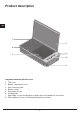
Product description EN 7 1 6 2 5 4 3 Integrated barbecue with thin cover 1. 2. 3. 4. 5. 6. 7. 8. Thin cover Battery compartment cover Gas connection point Burner controls Grill groups (2 sets) Cooking plate Removable oil collection drip plan located in front of the barbecue (not shown) Flame diffusers (2 pcs.
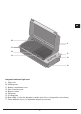
EN 10 9 15 16 11 14 13 12 Integrated barbecue high cover 9. High cover 10. Heating racks 11. Battery compartment cover 12. Gas connection point 13. Burner controls 14. Grill group 15. Cooking plate 16. Removable oil collection drip plan located in front of the cooking surface (not shown) 17. Flame diffusers (2 pcs.
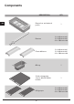
Components DESCRIPTION EN Burner box and external profile QTY 1 Burners 2 for 60cm model 3 for 80cm model 4 for 100cm model Flame diffusers 2 for 60cm model 3 for 80cm model 4 for 100cm model Oil tray 1 Solid cooking plate only for 80 and 100cm models.
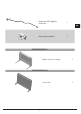
Universal LPG regulator and hose 1 EN Natural gas regulator 1 CONFIGURATION 1 High cover for cooking 1 CONFIGURATION 2 Low cover 7 1
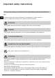
Important safety instructions For your own safety, you should read this manual before operating the barbecue. Use EN Carefully read the user manual and keep it in a handy place for future reference.
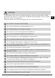
ATTENTION IF YOU SMELL GAS, do not try to light the barbecue. Perform the leak test procedure described in this manual. Locate the leak and tighten theleaking fitting; if it is the cylinder fitting, also replace the gasket seal. If the leak persists, turn off the gas supply and call for technical assistance. Do not lean over barbecue while lighting. Do not leave the barbecue unattended when it is on. Do not delay ignition once the gas is opened. Do not store or use aerosol sprays near the barbecue.
Do not modify this appliance. Do not place articles on or against this appliance. EN This appliance reaches high temperatures. Be especially careful when children and elderly persons are present Do not move the barbecue when it is on. Wear protective gloves when using the barbecue. Keep children under the age of eight years away, if not constantly supervised. Never attempt to extinguish a flame/fire with water: turn off the appliance and cover the flame with a cover or a fire blanket.
Assembling the barbecue Tools needed for assembly: - Phillips screwdriver 1. Remove all components from the box. EN BACK FRONT 2. Place the flame diffusers in the desired positions (under the points (A) in which the grill sections will be placed) and attach the rear edge of the flame diffuser to the rear of the body of the barbecue.
3. Apply the oil drip pans to the front of the barbecue.
4. Place the cooking plate and grill sections in the desired positions, making sure that the flame diffusers are under the grill sections. NOTE: Make sure that the grill groups are correctly oriented so that the surface of the grill is tilted forward to allow the oil to drain into the drip pan. EN 5. After installation in the counter, connect the thin cover or cooking hood area as described in the chapter “Application of the thin cover or cooking hood” in this manual.
GAS TYPE Model NATURAL GAS 100 80 60 UNIVERSAL LPG 100 80 60 Nominal heat input (MJ/h) 52 39 26 52 39 26 Injector diameter (1/100mm) 170 170 170 100 100 100 Number of injectors 4 3 2 4 3 2 Pressure (kPa) 1 1 1 2,75 2,75 2,75 2 All open Primary air regulation (mm) X Overall dimensions: 4 burner is 1000mm wide, 3 burner is 800mm wide, 2 burner is 600mm EN wide.
2 - Lower the burner and replace the injector.
NOTES • The appliance MUST only be installed and serviced by qualified and authorized personnel. • The product is exclusively intended for outdoor use. • The product must be installed according to the instructions, which require ventilation openings to allow the grill to work properly. The lack of adequate ventilation to supply air to the appliance can lead to poor operation of the burners or excessive heat build-up in the installation compartment.
Gas Connection I. For connection to 9Kg portable gas cylinders please refer to page 28 II. For connection to a fixed LPG Supply: It is possible to connect this barbecue to a fixed LPG reticulated piping system which may supply gas to other appliances in the building. The installation must be carried out by a licenced gas fitter in accordance with AS/NZS 5601 and any relative Building Code/Statutory Regulations.
Universal LPG regulator and braided hose 1 EN 50 490 45 AS/NZS 5601 (Gas Installations) Test point adaptorEnsure arrow is pointing In the right direction Hose with tapered thread (thread tape required) 18
CONVERSION PROCEDURE Normal LPG to NG I Hose with tapered thread - thread tape required • • • • • • • • • • Regulator - ensure arrow is pointing the right direction Disconnect and disassembled/remove trivet, burners etc. Install the Natural gas regulator incorporating the test point pressure nipple. Remove injectors and replace with correct sizes for each burner. Adjust aeration (X) per every burner Re-assemble burners. Turn gas on and test for leaks, repair if necessary.
EN X 20
Gas cylinder safety information • • • • • • • • When converted for the use of universal LPG, the appliance is designed to use different types of cylinders depending on the installation made. See the chapters on Installation Preparation and Connection of the cylinder. The gas cylinder must be manufactured and marked in accordance with the specifications for LPG cylinders. The shut-off valve must be closed when the appliance is not in use.
Installation instructions and warnings ATTENTION EN • • • • • • • • The appliance must only be used above ground level, in open air and natural ventilation without stagnant areas where leaking gas and combustion products are rapidly dispersed by the wind or natural convection. This barbecue is designed exclusively for outdoor use. Refer to the drawings below. Never install the barbecue inside buildings, garages, sheds or covered walkways, or in a boat, camper or caravan.
External surface area example 4 EN open side for at least 25% of the in total 30% or more of the remaitotal area of the walls ning surface of the walls is open and free External surface area example 5 open side for at least 25% of the in total 30% or more of the remaitotal area of the walls ning surface of the walls is open and free Selection of the point of installation • • • • • The appliance must not be installed on combustible materials.
Island-mounted • EN • If the appliance is installed in an island, it can be placed in the centre. Pay particular attention to the overall dimensions of the top of the island, taking into account the open cooking hood and its projection. See page 24. The required dimensions of the cut-out are 1025 mm x 505 mm for model 100 cm, 800 mm x 505 mm for mod. 80 cm and 585 mm x 505 mm for mod. 60cm (see drawing pag. 26/27).
To facilitate insertion in the cabinet, the product has specific lifting handles (see figure below) SX DX non-combustible wall non-combustible Top 135 194 584 35 25 215 70 minimum clearance to back wall non-combustible material Special opening for ventilation 25x700 mm wooden wall non-combustible Top 135 194 584 FRONT 35 25 215 200 minimum clearance to back wall non-combustible material Special opening for ventilation 25x700 mm 25 FRONT EN
non-combustible Wall non-combustible Top 215 135 54 564 70 35 25 EN minumum clearance to back wall FRONT non-combustible material Special opening for ventilation 25x700 mm woonden Wall non-combustible Top 135 54 564 35 25 215 200 minumum clearance to back wall non-combustible material Special opening for ventilation 25x700 mm non-combustible Top 215 135 Wall FRONT 35 25 70 minumum clearance to back wall non-combustible material 26 air inlet 10 FRONT
625 567 180 70 35 70 35 180 EN 505 505 Mod BBQ 100 cm 95 min Cut out 505 1025 Minimum distance From wall for cover rotation FRONT Mod BBQ 80 cm 95 min Cut out 505 800 Minimum distance From wall for cover rotation FRONT 27
EN Mod BBQ 60 cm 585 Cut out 505 95 min Minimum distance From wall for cover rotation FRONT ATTENTION • The appliance requires adequate ventilation. An opening for ventilation must be provided as shown on the following pages. A ventilation grate can be applied, if desired. This ventilation surface allows air to enter the compartment for the optimum combustion. In case of an island construction, this opening can be at the rear of the island.
Mod BBQ 100 cm The cylinder compartment must be ventilated in accordance with AS/NZS 5601, (Appendix J - Clause J3 - 4: Cylinders in an enclosure or recess), with the free ventilation area having at least 20,000 squared mm at high and low level.
Mod BBQ 60 cm The cylinder compartment must be ventilated in accordance with AS/NZS 5601, (Appendix J - Clause J3 - 4: Cylinders in an enclosure or recess), with the free ventilation area having at EN least 20,000 squared mm at high and low level.
ATTENTION The compartment below the barbecue unit must be isolated from the barbecue by a noncombustible panel. The compartment must comply with the requirements of AS/NZS 5601. If EN the barbecue is fuelled by LPG, ventilation openings must be made at the top and bottom of the compartment or cavity as shown in the drawings on pages 28 and 29, each of which must provide a free surface of at least 200 cm2 per cylinder housed or 700cm2 as shown if the LPG gas cylinder is located elsewhere.
EN Min 300 mm 215 mm Min 300 mm Min 200 mm Min 200 mm non-combustible barrier necessary under the barbecue MAX 1,5 mt cut a hole in the non-combustible barrier only for the hose front of the compartment emoved for clarity 32
The LPG cylinder may be connected inside the object-holder compartment of barbecue only if it has the dimensions shown in the guidelines. The safe use of a cylinder inside the object-holder compartment of the barbecue depends on several factors: A) The base of the cylinder must be properly inserted between the plates and be horizontal on the base panel.
Application of the thin cover Application of the low cover • Remove the thin cover from the packaging. • Attach the hinges to the outer frame and secure it with the special screw provided.
Application of the high cover • Remove the High cover from the packaging. • Remove the hinge from the cover and apply it to the outer frame. Fix it with the special screws provided. • Insert the cover into the seats of the hinge. IMPORTANT • • Given the dimensions of the cooking hood, we recommend that two people position it. During positioning the high cover group, take special care to avoid scratching the external profile.
Usage instructions IMPORTANT Make sure that the flame diffusers are positioned flame under the panels of the grills EN BBQ 100 Solid cooking plate on the left, double grill on the right - best orientation for grilling BBQ 100 half grill on the left, central solid cooking plate, hal grill on the right - best orientation for roasting 36
EN BBQ 80 total grill BBQ 80 Solid cooking plate on the left, grill on the right - best orientation for grilling BBQ 60 total grill 37
Control functions Before lighting the barbecue: • Check that all the gas hoses and fittings are tight. • Open the thin or high cover. EN Gas leakage detection test Never use a match or flame, use soapy water solution and spray or brush the solution onto all connections. Carefully check for bubbles which indicate a gas leak. If leaks are detected, turn the gas off and retighten connection(s), then repeat test. The fittings must be thoroughly rinsed with clean water after testing.
Manual lighting • If the automatic ignition system is not working, the barbecue can be lit manually. • To turn it on manually, use a long match (28cm). Pass the lit match between the inspection slots under the front part of the hob, approaching it to the burner, then turn the knob and hold it pressed on MAX (quick preheating) in order to perform the ignition. If it does not light, close the control valve and wait a few minutes for the gas to disperse before trying to light the barbecue again.
• • In case of uncontrolled sudden flames, remove the food from the fire until the flame is damped. To roast with the high cover closed, it is sufficient to adjust the 4 burners to the minimum power (MIN) for satisfactory cooking EN To turn off the burner • When done cooking, turn the knob fully clockwise so that the mark on the knob is in the closed (O) position. Remember to always close the valve of the gas cylinder after use. Remember to shut-off the gas before closing the cover.
Cleaning and care Care and cleaning of the appliance To preserve its appearance, we recommend cleaning the cooking surfaces after each use. Where the unit is exposed to the elements, we strongly recommend the optional cover. Other surfaces must be maintained regularly to protect the unit from tea staining and rusting. EN ATTENTION Make sure the barbecue is turned off and has cooled down before executing the instructions shown below.
3 mm 3 mm EN Cleaning the grease drip pan The integrated barbecue has a unique oil management system that uses overlapping channels to convey all the oil towards the front to easily removable drip pans, which must be cleaned after each use. • To remove the drip pan, pull them upwards from the front of the barbecue; dispose of their contents in a responsible way. Wash the collection pans in hot soapy water or, if you want, you can put them in the dishwasher.
2 - Move the drawer EN 3 - Raise up the pan up Burners The burners should be checked at least once a year and cleaned if necessary. Inspect the burners to make sure that no residue deposits and that the gas connections are free. SUGGESTIONS AND INFORMATION Special note on “tea staining” Sometimes stainless steel surfaces are affected by a colour change called “tea staining”. This usually occurs in areas where high heat is used and can be removed using stainless steel cleaning agents.
Maintenance Ignition system To change the battery, remove the battery cover by lifting the battery holder flap on the left side and pull out the battery. Replace it with a new D battery and replace the cover. Perform a test by pressing the knob; you should hear a click. EN Ventilation openings The ventilation openings of the installation compartment must be inspected before each use of the appliance to make sure that there are no obstructions that could impede the free flow of air.
Troubleshooting PROBLEM POSSIBLE CAUSE SOLUTION The barbecue doesn’t light No gas Check that the shut-off valve is open (ON) Gas cylinder empty - refill or change the cylinder The ignition system is not working Check the battery - you should hear a clicking sound when you press the knob Replace the battery Light the barbecue manually Gas tap regulated too high Clean and delicately dry the electrode making sure that its position is correct Excessive smoke from the cooking surface Gas valve set to
EN MANUFACTURER’S DECLARATION The manufacturer declares that, depending on their type, the products in this catalogue conform to the fundamental requirements of European Directives and, for this reason, the product bears the CE mark, for which this declaration of conformity was issued and made available to market supervisory bodies.
Warranty Card Worldwide Appliances Pty Limited A.B.N. 45868077422 Office: 48-50 Moore Street, Leichhardt N.S.W 2040 Post: Locked Bag 3000, Annandale, N.S.W 2038 P: 1300 694 583 WARRANTY REGISTRATION Your ongoing satisfaction with your artusi product is important to us. We ask that you complete the enclosed Warranty Registration Card and return it to us so that we have a record of the artusi product purchased by you.
Warranty Card continued 4. Time for Claim under the Warranty You must make any claim under this Warranty within twenty eight (28) days after the occurrence of an event which gives rise to a claim pursuant to the Warranty, by booking a service call on the telephone number below. 5. Proof of Purchase Customers must retain proof of purchase in order to be eligible to make a warranty claim in respect of an artusi product. 6.
cod. 1.009.87.4 - 01/2021 DISCLAIMER Worldwide Appliances PTY LTD, trading as ARTUSI, is continually seeking ways to improve the design specifications, aesthetics and production techniques of its products. As a result alterations to our products and designs take place continually.