
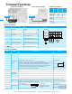
Specifications
Applicable Wiring Apparatus and Options
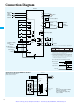
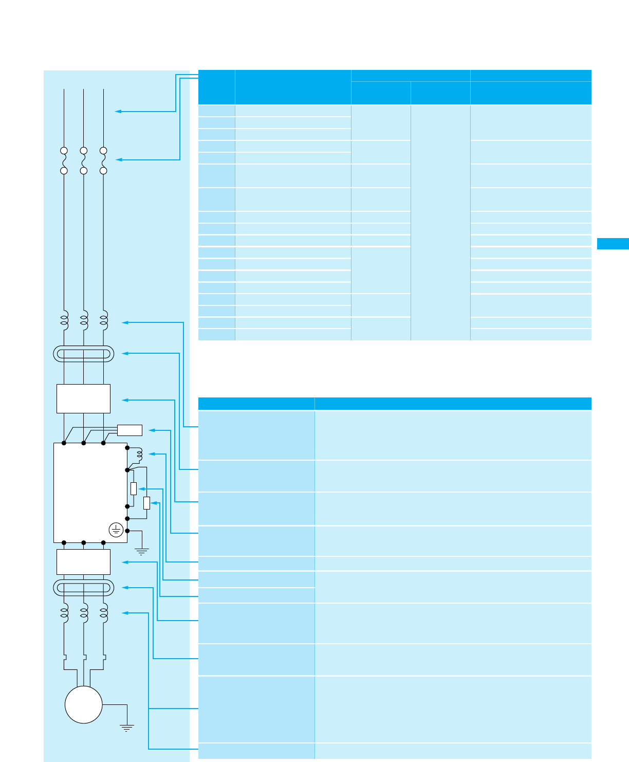
(Power supply)
L1 L2 L3
T1 T2 T3
+1
+
-
RB
Inverter
Motor
Thermal
relay
IM
Fuse
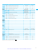
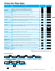
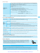
Function
This is useful when harmonic suppression measures must be taken,
when the main power voltage unbalance rate exceeds 3% and the
main power capacity exceeds 500kVA, or when a sudden power
voltage variation occurs.It also helps to improve the power factor.
Noise may occur in a nearby radio, etc., via the mainpower supply
side wiring when using the inverter. This filter helps to reduce the
noise; radiated noise reduction.
Reduces the conductive noise on the main power wires generated
from the main power supply. Connect to the inverter primary side
(input side).
Reduces noise radiated from the main power wiring on the input side.
Suppresses harmonics generated by the inverter.
This is useful for increasing the control torque of the inverter, for
frequently repeating ON-OFF of the inverter, or for decelerating the
load with a large inertial moment (GD
2
).
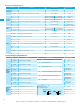
This is installed between the inverter and the motor to reduce noise
radiated from the control power wiring. It is useful for reducing
radio-wave disturbance in a radio or TV set and for preventing
malfunction of measuring instruments or sensors
Useful for reducing noise produced in the inverter output side.
(It is usable on either the input or output side.)
Vibration may increase when driving a general-purpose motor with an
inverter as compared with operation on commercial power.
Connecting this reactor between the inverter and the motor allows
reduction of motor pulsation. When the wiring between the inverter and
the motor is 10 m or more, inserting the reactor prevents thermal relay
malfunction caused by harmonics resulting from inverter switching.
A current sensor can be used instead of the thermal relay.
Output-side sine wave generating filter
Name
Input-side AC reactor for
harmonicsuppression/power
coordination/powerfactor
improvement
(ALI-
w w w
2
)
Radio noise filter
<zerophase reactor>
(ZCL-
w
)
EMI filter for Inverter
(FFL100-
w w
)
Input-side radio noise filter
(capacitive filter)
(CFI-
w
)
DC reactor
Output-side noise filter
(ACF-C
w
)
Radio noise filter
<zero-phase reactor>
(ZCL-
w w w
)
AC reactor for vibration
reduction/thermal relay
malfunction prevention
(ACL-L2-
w w w
)
(ACL-H2-
w w w
)
LCR filter
Standard Apparatus
Options
Note 1: FFL100 series filter is required for EMC directive(Europe),C-Tick(Australian EMC requirment) but the other
options are not for these purpose. Reactors and filters except for EMI filter listed above are for general use in
noise reduction.
Note 2: Fieldbus communications -Please consult your sales representative or distributor for available options.
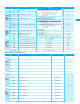
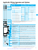
Motor
Output
(kW)
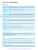
Inverter model
Wiring
Applicable equipment
Power lines
Signal lines
Fuse(class J)
rated 600V
0.2
0.4
0.55
0.75
1.1
1.5
2.2
3.7
5.5
7.5
0.4
0.75
1.5
2.2
3.0
4.0
5.5
7.5
AWG14/2.1mm
2
AWG16/1.3mm
2
AWG14/2.1mm
2
AWG12/3.3mm
2
AWG12/3.3mm
2
AWG12/3.3mm
2
AWG10/5.3mm
2
AWG8/8.4mm
2
AWG10/5.3mm
2
AWG16/1.3mm
2
10A
15A
30A
6A
3A
50A
40A
10A
10A
15A
20A
25A
25A
(
single ph.
)
15A
(
three ph.
)
30A
(
single ph.
)
20A
(
three ph.
)
NOTE1: Field wiring connection must be made by a UL Listed and CSA Certified closed-loop terminal connector sized for the wire
gauge involeved. Connector must be fixed using the crimp tool specified by the connector manufacturer.
NOTE2: Be sure to consider the capacity of the circuit breaker to be used.
NOTE3: Be sure to use bigger wires for power lines if the distance exceeds 20 m.
(*) Use 0.75 mm
2
wire for the alarm signal wire.
(*)
0.14 to 0.75
mm
2
Shielded wire
SJ100-002NFE/NFU
SJ100-004NFE/NFU
SJ100-005NFE
SJ100-007NFE/NFU
SJ100-011NFE
SJ100-015NFE/NFU
SJ100-022NFE/NFU
SJ100-037LFU
SJ100-055LFU
SJ100-075LFU
SJ100-004HFE/HFU
SJ100-007HFE/HFU
SJ100-015HFE/HFU
SJ100-022HFE/HFU
SJ100-030HFE
SJ100-040HFE/HFU
SJ100-055HFE/HFU
SJ100-075HFE/HFU
16
Braking resistor
Braking unit
Artisan Technology Group - Quality Instrumentation ... Guaranteed | (888) 88-SOURCE | www.artisantg.com