
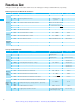
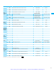
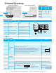
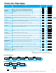
Specifications
t 2.0
L1
L2
L3
P24
1
2
3
5
6
O
O
L
FM
L
H
DC10V
CM2
12
11
AL0
RB
+
-
+1
T3
T2
T1
AL1
AL2
L
L
L
4
L
L
5V
L
RY
RY
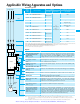
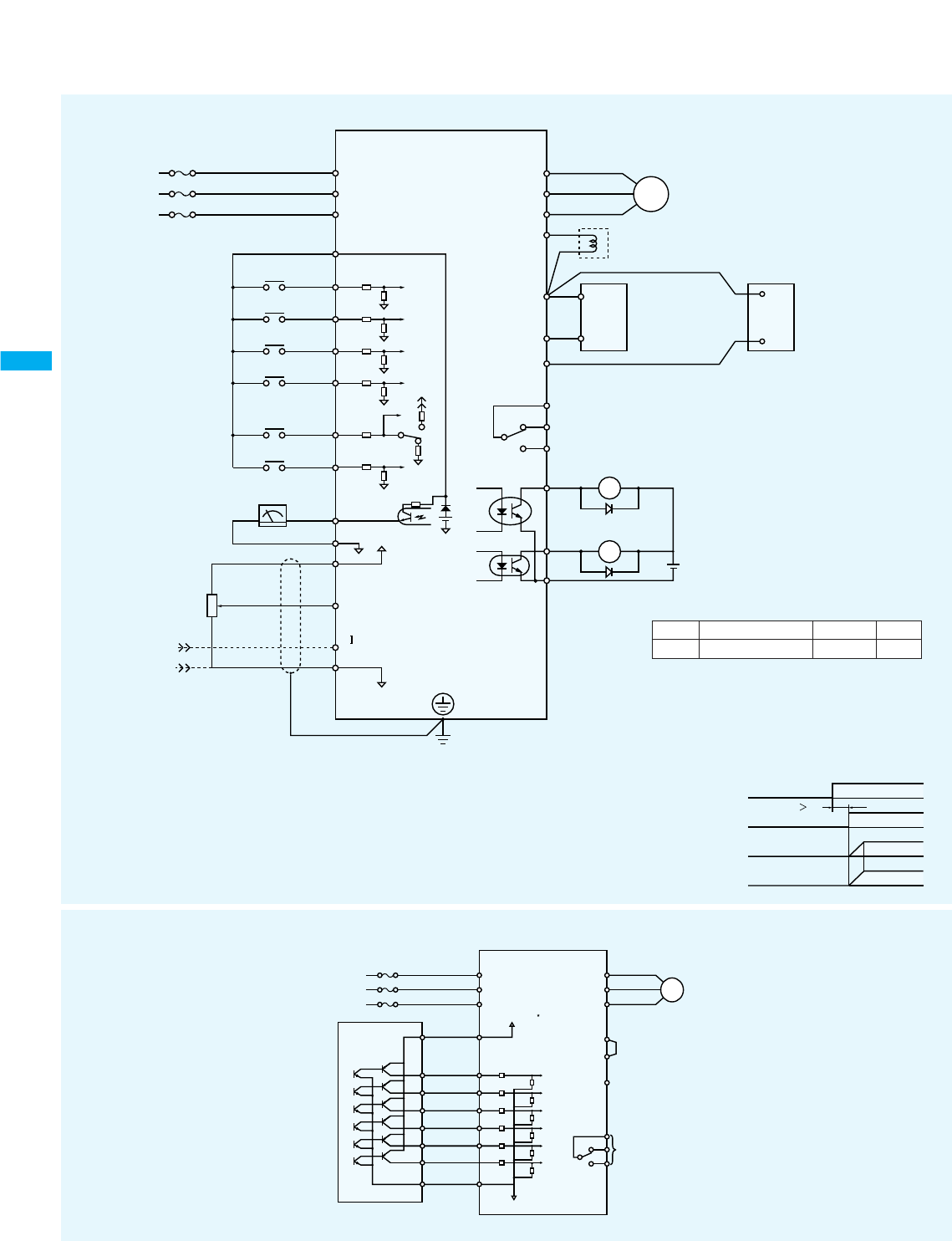
DC24V
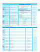
4~20mA
Current input
COM
Inverter common
EH-YTP16 type
transistor output module
INVERTER
1
P24
L3
L2
L1
W
V
U
2
3
4
5
L
1
2
3
4
5
6 6
S
24 VDC
Motor
+1
+
RB
AL0
AL1
AL2
Alarm output
contact
1
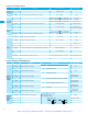
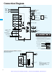
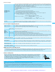
Connection Diagram
Main power
supply
3-phase
200~230V
50/60 Hz
Inverter
Class 3 grounding
Main circuit power
RUN command
Output frequency
Motor rpm
(*3)
Motor
DCL
(DC reactor) (option)
Frequency setting
device
1kΩ~2kΩ
Dynamic
braking
resistor (option)
Dynamic
braking
unit (option)
Alarm relay output
Turn on the main power at the timing shown below.
*1: Note that the common terminal differs depending on
the terminal name.
1, 2, 3, 4, 5, 6 FM, H, O, OI 11, 12
P24 L CM2
Terminal
Name
*2: The braking resistor is equipped with a
thermosensor. If it is activated, turn off the main
power or extend the deceleration time.
*3: Use the above timing to turn on the main power and
input the RUN command. If the main power ON
and the RUN command input occur simultaneously,
the motor starts to run 2 sec. later because the
control power supply boot is delayed.
Common
15
<Connection to the Programmable Controller>
When the internal interface
power source is used
Note 1:
Do not short circuit the terminals
P24 and L by mistake.
The control power supply may
cause a failure
(0.3W or more
is recommended)
Artisan Technology Group - Quality Instrumentation ... Guaranteed | (888) 88-SOURCE | www.artisantg.com