
Specifications
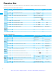
Function
L1,L2,L3
G
T1,T2,T3
+, +1
+,
-
+, RB
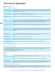
Symbol
007~022NFE
007~022NFU
037LFU
004~040HFE
004~040HFU
055~075LFU
055~075HFE
055~075HFU
002~005NFE
002~004NFU
M3.5 M4 M5
Main
circuit
terminal
Alarm
terminal
Control
circuit
terminal
M2 (press-tight type)
M3 (press-tight type)
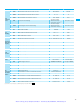
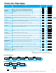
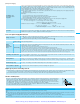
Terminal Functions
Main circuit
terminal
Main power supply input
terminals
Inverter output terminals
DC reactor connection
terminals
External braking resistor
connection terminals
External braking unit
connection terminals
Ground connection terminal
Main Circuit Terminals
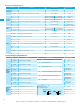
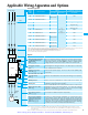
Control Circuit Terminals
Connect the input power
supply.
Connect the motor.
Connect the DC reactor for
harmonic suppression, power
factor improvement.
Connect the optional
regenerative braking resistor
when braking torque required
Connect the optional
regenerative braking unit
when braking torque required
Ground to prevent electric
shock and reduce noise
FM
L
P24
6
5
4
3
2
1
H
O
OI
L
12
11
CM2
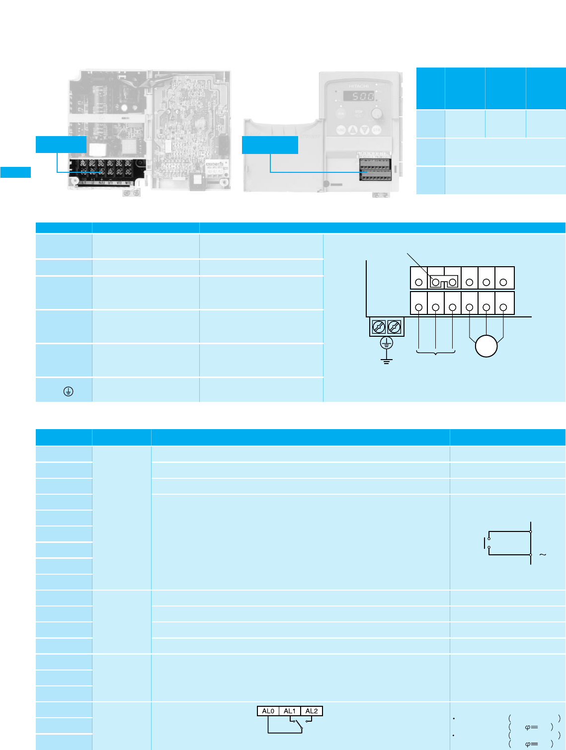
AL2
AL1
AL0
Symbol
Frequency
command
Alarm output
Output signal
Input/Monitor
signal
Signal
Monitor terminal (frequency, current, etc.)
Common terminal for monitor and frequency command
Common terminal for the intelligent input terminal
Power supply (10VDC) for frequency command
Frequency command input (voltage command) (0 ~ 10VDC)
Frequency command input (current command) (4 ~ 20mADC)
Common terminal for frequency command
Intelligent output terminal, selection from:
Run signel (RUN), Freguency arrival at the set freguency signal (FA1), Freguency arrival at
or aboue the set freguency signal (FA2), Overload advanced notice signal (OL), Output
deviation for PID control (OD), and Alarm signal (AL).
Intelligent input terminals, selection from:
Forward run command (FW), Reverse run command (RV), Multispeed
commands 1~4 (CF1~CF4), 2-stage acceleration/deceleration command (2CH), Free-run
stop (FRS), External trip (EXT), Unattended start protection (USP), Jogging (JG),
Analog input selection (AT), Software lock (SFT), Reset (RS), PTC Thermistor thermal
protection (PTC), External DC braking (DB), Set second motor (SET), and
Remote control acceleration/deceleration(UP/DWN)
Terminal Name
Open collector output
L level at operation (ON)
PWM output
-
24 VDC
-
Input impedance 10 kΩ
Input impedance 250Ω
-
Contact input
Operated by SW (closed)
Remarks
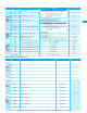
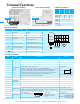
Front case (right open)
Terminal section cover (left open)
[Main Circuit Terminal] [Control Circuit Terminal]
Terminal Screw Diameter
Control circuit
terminal
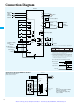
LOWER
L1
RB
L2
+1 +
-
N/L3 T1/U T2/V T3/W
UPPER
Short bar
Motor
Ground
Power supply
(Power source)
SW
P24
6
1
Contact rating
0.4
AC250V 2.5A
resistor load
DC30V
0.2A
cos 0.4
3.0A
resistor load
cos0.7A
Alarm output terminal:
NO-NC contact (relay) output
Common with intelligent output terminal
<Initial Setting>
Normal:AL0–AL1 closed
Trip/Power OFF:AL0–AL2
closed
13
Terminal Name
Artisan Technology Group - Quality Instrumentation ... Guaranteed | (888) 88-SOURCE | www.artisantg.com