
Installation Sheet

Design: Michele De Lucchi, Gerhard Reichert
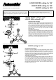
LOGICO MINI ceiling 3 x 120˚
LOGICO MICRO ceiling 3 x 120˚
Avis:
Déconnecter la tension de réseau avant toute opération sur l’appa-
reil.
Employer exsclusivement les ampoules du type et de la puissance
indiquée sur la plaque de l’appareil.
Note:
Prior to any work on the fixture always switch off the mains.
Onlyusebulbsofthetypeandwattageindicatedontheratingplate.
LOGICO MINI ceiling 3 x 120˚
LOGICO MICRO ceiling 3 x 120˚
LOGICO ceiling 3 x 120˚
fig. 1
fig. 2
LOGICO ceiling 3 x 120˚
G
E
E
F
F
F
G
C
C
C
D
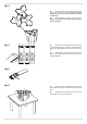
Instructions de montag e.
Dévisser les vis C pour séparer le corps de la lampe D du culot E.
Dévisser les vis F pour séparer la plaque G du culot E.
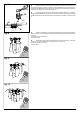
Brancher les
câbles en connectant le câble blanc d e l’appareil au câble blanc de la boîte
à mur et le câble noir de l’appareil au câble noir. Brancher le câble vert aussi
au conducteur de terre.
Fixer le culot E alaboiteamur.Fixerlaplaque
G au moyen des vis F.FixezlecorpsdelalampeD au culo t E en
serrant les vis C.
Assembly instructions.
Loosen the screws C to separate the lamp body D from the base E.
Loosen the screws F to separate the plate G from the base E.
Make
electrical connections by connecting the white wire from the fixture to the
white wire from the wall box and the fixture black wire to the black wire. Also
connect the green wire to the system ground conductor.
Fix the base E
to wall box. Fix the plate G by tightening the screws F. Anchor the
lamp body D to the base E by tightening the screws C.
G
E
A
E
G
F
F
F
C
C
C
D
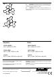
Instructions de montag e.
Dévisser les vis C pour séparer le corps de la lampe D du culot E. Dévisser
les vis F pour séparer la plaque G du culot E.
Brancher les câbles en connectant
le câble blanc de l’appareil au câble blancde laboîte à mur et le câble noir de l’appareil
au câble noir. Brancher le câble vert aussi au conducteur de terre.
Fixer la plaque
A au plafond. Fixer le culot E alaplaqueA.FixerlaplaqueG au moyen des
vis F.FixezlecorpsdelalampeD au culot E en serrant les vis C.
Assembly instructions.
Loosen the screws C to separate the lamp body D from the base E. Loosen
the screws F to separate the plate Gfrom thebase E.
Makeelectricalconnections
by connecting the white wire from the fixture to the white wire from the wall box and
the fixture black wire to the black wire. Also connect the green wire to the system
ground conductor. Fix the plate A to the ceiling.
Fix the base E to the plate A.Fix
the plate G by tightening the screws F. Anchor the lamp body D to the base
E by tightening the screws C.