Transporter Assembly Instructions is a registered trademark of Artec Co., Ltd. in multiple countries including Japan, South Korea, Canada, and the USA.
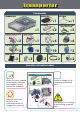
Transporter Components Studuino Unit USB Cable Battery Box x1 DC Motor x1 Reflective Infrared Sensor IR Photoreflector Touch Sensor x1 x2 x4 Half D (aqua) O-ring x2 x2 x19 Wheel x2 x3 x4 x8 Hub Sensor Connecting Cable (three-wire 15 cm) Triangle A (gray) Half C (light aqua) Half B (blue) Half A (light gray) Rotor Axis C Basic Cube (white) Touch Sensor x2 x2 x1 Disk x2 x2 x2 Assembly Instruction Labels Transporter x1 Shows the parts needed for assembly.
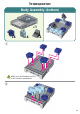
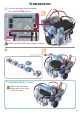
Transporter Body Assembly (bottom) x1 x4 x4 x2 ① Make sure the Studuino unit is in the correct orientation! ② 03
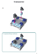
Transporter ③ Completed Body (bottom) 04
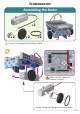
Transporter Assembling the Motor x2 x2 x2 x2 M1 M2 ① Connect the assembled DC Motor to M2. M2 M2 Make sure the cables are inserted correctly! Slip the O-ring onto the grooves of the wheel.
Transporter ② Connect the assembled DC Motor to M1. M1 Make sure the cables are inserted correctly! M1 Slip the O-ring onto the grooves of the wheel.
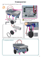
Transporter Body Assembly (front) x1 x1 x2 x3 x2 x2 x7 x1 ① 07
Transporter ② Connect the touch sensor to A4. Sensor Connecting Cable Sensor side Circuit board side Touch Sensor A4 Black Gray Make sure the cables are inserted correctly! ③ Make sure the cables are inserted correctly! Connect the reflective infrared sensor (IR Photoreflector) to A2.
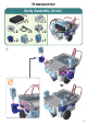
Transporter ④ Connect the reflective infrared sensor (IR Photoreflector) to A3. Black Gray IR Photoreflector A3 Make sure blocks are inserted correctly! ⑤ Make sure the cables are inserted correctly! ⑥ You should see the battery box switch here.
Transporter ⑦ Connect the cable from the battery box to the POWER section. POWER Make sure the cables are inserted correctly! ⑧ Completed Body (front) Make sure the sensor cables are on the sides of the car body.
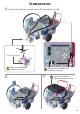
Transporter Assembling the Head and Arms x4 ① x2 x2 x8 x1 x2 x2 Attach first.
Transporter ② Rotor axis stud should be inserted into the side. Make sure blocks are inserted correctly! ③ Rotor axis stud should be inserted into the side.
Transporter ④ Left Side Half B (blue) Half C (light aqua) Touch sensor Do not insert the Half B (blue) studs into Half C (light aqua). Push the Half B (blue) block down with your finger, as illustrated, so that it is pushing down on Half C (light aqua). Half C (light aqua) should be inserted into the touch sensor.
Transporter Replacing the Batteries ① ② ③ ④ ⑤ Use a screwdriver (Phillips #1) to open. Insert batteries in the correct polarity. Put the lid of the battery box back in place.
Transporter Completed Transporter Be cautious of cables that could become entangled in the moving parts of the motor and cause the robot to disconnect. Arrange cables with caution. Before operating your robot, check the assemby instructions again to confirm your robot has been assembled correctly.
Transporter Making Your Transporter Run Install the software from the URL below to setup the Studuino Programming Environment. ★ Proceed to Step 1 when software installation is complete. http://www.artec-kk.co.jp/studuino/ ① ② Connect the USB cable to the PC and the Studuino unit. Refer to 1.3. About Studuino in Studuino Programming Environment Manual for more details. Download the program file Transporter.ipd from the URL below in the ArtecRobo section. http://www.artec-kk.co.
Transporter Making Your Transporter Run ⑥ On the last page of the instructions there is an A4 size printout of a run course for your robot. If you cannot print out the course, you can draw your own. Draw the lines of the run course using a thick, black marker and white paper. The thickness of the lines should be between 5 mm and 10 mm. Your robot cannot make sharp turns. ⑦ Place the robot onto the course where the left and right reflective infrared sensor can detect the course line.
Transporter Sensor Calibration Some sensors may not function properly after you run the program for the first time. If the sensors are malfunctioning, calibrate the sensor settings. Click the sensor icon in the box and you can adjust the range settings in the condition box below. Drag the mouse left or right to adjust the range settings. Refer to the Condition Icon sections in 4.4. The Attribute Field of the Studuino Programming Environment Manual for more details.
Transporter Robot Course