PRO MPA II ™ ART PRO MPA II Microphone Preamplifier USER’S GUIDE
IMPORTANT SAFETY INSTRUCTIONS – READ FIRST This symbol, wherever it appears, alerts you to the presence of uninsulated dangerous voltage inside the enclosure. Voltage that may be sufficient to constitute a risk of shock. This symbol, wherever it appears, alerts you to important operating and maintenance instructions in the accompanying literature. Please read manual. Read instructions: Retain these safety and operating instructions for future reference. Heed all warnings printed here and on the equipment.
IMPORTANT SAFETY INSTRUCTIONS – READ FIRST ......................................................... II PRO MPA II OVERVIEW – FEATURES AND GENERAL INFORMATION: ............................ 1 FRONT PANEL CONNECTIONS AND CONTROLS ................................................................ 3 Input Gain control ..................................................................................................................................... 3 Input Impedance control ......................................
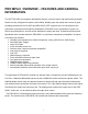
PRO MPA II OVERVIEW – FEATURES AND GENERAL INFORMATION: The ART PRO MPA II microphone preamplifier features a new low noise, high performance preamplification circuitry, designed for superior audio fidelity. Building upon the quality and success of great sounding products like the Pro MPA and MPA GOLD, ART engineers set out to develop the next generation of professional microphone preamplifier. PRO MPA II is the culmination of years of research and development, and sets a new standard for quality and value.
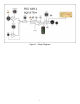
Figure 1 – Block Diagram 2
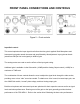
FRONT PANEL CONNECTIONS AND CONTROLS Figure 2 – Front controls Input Gain control This control optimizes the input signal level before the tube gain is applied. Both Microphone and Instrument input gains remain the same and are affected by this adjustment. Input gain can be adjusted from 0dB (for line level signals) to 40dB of gain. The analog meters are used to see the effects of the input gain setting.
with the PRO MPA II ” for more detailed instructions on setting the Input Gain control for the best results. Input Impedance control This knob controls the Mic/line input amplifier impedance. This function allows variable voicing of any microphone. Refer to the application section titled “Adjusting the Input Impedance” for more information on making the most of this function. The ¼” instrument input is NOT affected by this control, and remains high (>1M Ohm) impedance.
Phantom switch Phantom power on the microphone input is turned on and off with this switch. Depressing the switch will power condenser microphones and other 48volt phantom powered devices. Phantom power is supplied to pins 2 and 3 of the input jack. NOTE: 1) Dynamic microphones are NOT affected by Phantom power, although it should be turned off when using dynamic microphones or line level inputs. 2) Although the 48volt phantom power ramps up and down slowly it may still create a pop.
In the “Normal” (OUT) position, the tube distortion gradually rises until it smoothly clips. The tube is run almost completely open-loop in this mode, providing a musical tube “crunch” when overdriven with a natural recovery from clipping. The tube section can be more easily overdriven when the gain switch is in. This mode brings out the harmonics in the input sources, particularly stringed instruments. The tube circuit runs extremely clean in the “High” (IN) position of the plate voltage switch.
In Stereo mode, CH1 output adjusts the output gain of both channels and CH2 output control acts as a power summed Balance control. There is a slight drop in output level in stereo mode when the Balance knob is centered vs. at one extreme or another. When the switch is in the “Dual” position the output controls act on only their respective channels. +4/-10 switch (rear panel) The +4/-10 switch is used to set the output level of the PRO MPA II for the appropriate system levels.
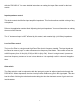
Rear Panel connections Figure 3 – Rear connections Balanced Inputs The PRO MPA II ’s XLR connectors follow the AES standard of Pin 1 = Ground, Pin 2 = Hot (+), Pin 3 = Cold (-). The Balanced inputs have an input impedance that is variable from 150 to 3K Ohms via the front panel control. The Maximum input level is +19dBu balanced and +17dBu unbalanced. Balanced Outputs The PRO MPA II ‘s flexible active balanced outputs are available on both ¼” and cannon connectors.
PRO MPA II OPERATING INSTRUCTIONS Obtaining the best noise performance with the PRO MPA II Start by turning down the Input Gain knob and centering the Analog Output knob. Use the analog meter to view the operating level by depressing the switch under the center of the analog meter. The meter will now indicate how much tube headroom there is. Set the +20dB switch to the out position. Increase the Input Level knob until the meter reads above –10dB.
We provide a continuously variable impedance control to allow you to fine-tune the voicing, finding the perfect interaction between microphone and pre-amp. Start by setting the centering the Input Impedance knob. This provides a 600-Ohm load. Lower impedance loads will reject more noise picked up by cabling, and dampen microphone resonance. Higher impedance settings provide a more “open” sound. Lower impedances tend to focus the sound more.
Using the Mid/Side mode The PRO MPA II is designed for stereo operation using the Mid/Side switch and two microphones. One of the mics needs to have a figure-8 pickup pattern. Start by aligning two mics 90 degrees apart. Connect the mic facing front (with an omni-directional or cardiod pickup pattern) to CH1. Face the front of the figure-8 pickup mic to the left side and connect it to the CH2 input. Depress the Mid/Side Matrix switch and center both of the Output Gain controls.
WARRANTY INFORMATION Limited Warranty Applied Research and Technology will provide warranty and service for this unit in accordance with the following warrants: Applied Research and Technology (A R T) warrants to the original purchaser that this product and the components thereof will be free from defects in workmanship and materials for a period of three years from the date of purchase.
SERVICE The following information is provided in the unlikely event that your unit requires service. 1) Be sure that the unit is the cause of the problem. Check to make sure the unit has power, all cables are connected correctly, and the cables themselves are in working condition. You may want to consult with your dealer for assistance in troubleshooting or testing your particular configuration. 2) If you believe the ART unit is at fault, go to www.artproaudio.com.
PRO MPA II SPECIFICATIONS Frequency Response ............................ 15Hz to 48 kHz (+0, -1dB) @ normal plate voltage 15Hz to 120 kHz (+0, -1dB) @ high plate voltage Dynamic range:..................................... >110dB (“A” weighted) CMRR: .................................................. >90dB THD: ..................................................... <0.005% (typical) Equivalent Input Noise: ......................... -129dBu (XLR, “A” weighted) Maximum Input Level: ...........................
NOTES: 15
16
www.artproaudio.com E-mail: cserve@artproaudio.