
User`s manual

4200 Series LaserSource User’s Manual · Page 13
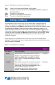
Menu Description Factory
Default
Im limit This setting controls the maximum amount of
monitor photodiode current the unit will
allow. This limit is implemented in software.
For more information about limits, see the
section entitled “Hardware and Software
Limits”.
Maximum
Po limit This setting controls the maximum amount of
monitor photodiode power the unit will allow.
This limit is implemented in software. For
more information about limits, see the
section entitled “Hardware and Software
Limits”.
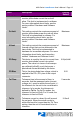
Maximum
Vf limit This setting controls the maximum amount of
forward current that can be delivered to the
laser diode. This limit is implemented in
hardware for immediate response. For more
information about limits, see the section
entitled “Hardware and Software Limits”.
Maximum
PD Resp This factor is used by the unit to convert from
monitor photodiode current into optical
power. The value is in terms of microamps
per milliwatt (μA/mW), such that power =
photodiode current divided by the factor.
0.00μA/mW
PD Bias This is the photodiode bias voltage, which is
applied to the PD+/PD- pins of the output
connector.
5.0V
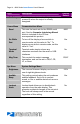
Tol Time Tolerance time is the amount of time, in
seconds, that the measured value (current,
voltage, etc.) must be within the set point +/-
the tolerance for the unit to be considered in
tolerance. In Io modes, the tolerance is
defined by Tol Io. For Im/Po modes, the
tolerance is fixed at 50uA. For Vf mode, the
tolerance is fixed at 50mV.
5 seconds
Tol Io Tolerance current is a band (in mA) around
the set point. When the actual current is
within this band for longer than the Tol Time
setting, then the unit is considered to be in
tolerance.
10.0mA