
User`s manual

4200 Series LaserSource User’s Manual · Page 11
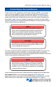
When the unit is in remote mode, the yellow Remote LED will be lit. More
information about how the instrument behaves in remote mode can be found in
the Remote Mode Operation section below.
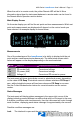
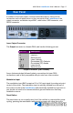
Main Display Screen
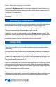
On the main display you will find the set point and two measurements. Which set
point and measurements are displayed will depend on the control mode you
have selected. An example display is shown below:
Sample Display
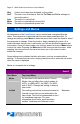
Measurements
One of the advantages of the LaserSource is its ability to display both the set
point and two measurements simultaneously. The table below shows which
values will appear on the display depending on the mode selected:
Mode Setpoint Displayed Measurements
Io Current (mA) PD current or power and voltage
Im PD current (μA) Current and voltage
Po PD power (mW) Current and voltage
Vf Voltage (V) Current and PD current or power
The instrument will show photodiode current or photodiode power, depending
on the value of PD Resp. Photodiode current is shown whenever PD Resp is
zero, while photodiode power will be shown whenever PD Resp is non-zero.
See the Control Modes section below for more information on the various
modes.
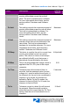
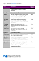
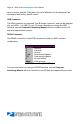
Status Messages
The instrument will display status messages in the upper-right corner of the
display indicating several different conditions that may be of interest to the user.
If multiple conditions exist simultaneously, then the instrument will cycle through
each condition, displaying each status message for approximately one second.
Possible condition messages are:
Lock The interlock is open and the unit cannot be turned on.