
User's Manual
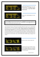
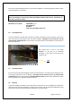
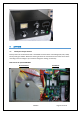
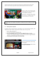
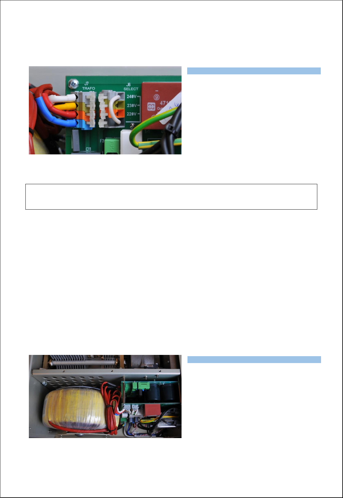
Exhibit 6 Page 33 from 35
Remove the upper lid first. On the right side of the PA, next to the HV transformer there are two
PCBs mounted. On the left upper side of the front (Switch-ON) board connector J6 is located.
Use flat screwdriver or finger and press
carefully the white stick to release contact
and move upper end of the white jumper to
the proper position, if necessary.
Jumper must be connected between bottom
contact and one of remaining contacts. AC
voltage is marked next to every contact.
NOTE
AC selector range can be changed in the production according to the specific conditions in individual
countries.
7.2. Removing the HV Transformer
For simpler and easier transport of the PA, HV transformer can be removed and taken separately. This
distributes the weight of the PA (24 kg) about half and half. Follow next steps to do it.
1. Remove upper lid from the PA.
2. Turn the PA on the left side (transformer is up).
3. Disconnect 3 connectors from the front board and 1 connector from the rear board.
4. Release 4 screws from the bottom side of the PA. Use Philips screwdriver P2. During the release
of the last 2 screws hold the transformer by hand. Do not worry about its weight, it will move
down just 1 cm and remains on the central rung of the PA.
5. Use both hands to take transformer away from the chassis.
Watch the released terminals, when moving
the transformer!
Do not damage transformer insulation during
removing and transportation.
Type of supported TCVR and working
frequency are visible on the display.
AUTO LED is ON.
Type of supported TCVR and working
frequency are visible on the display.
AUTO LED is ON.