
User's Manual
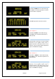
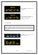
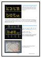
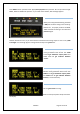
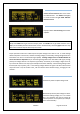
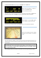
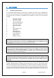
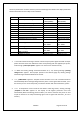
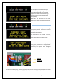
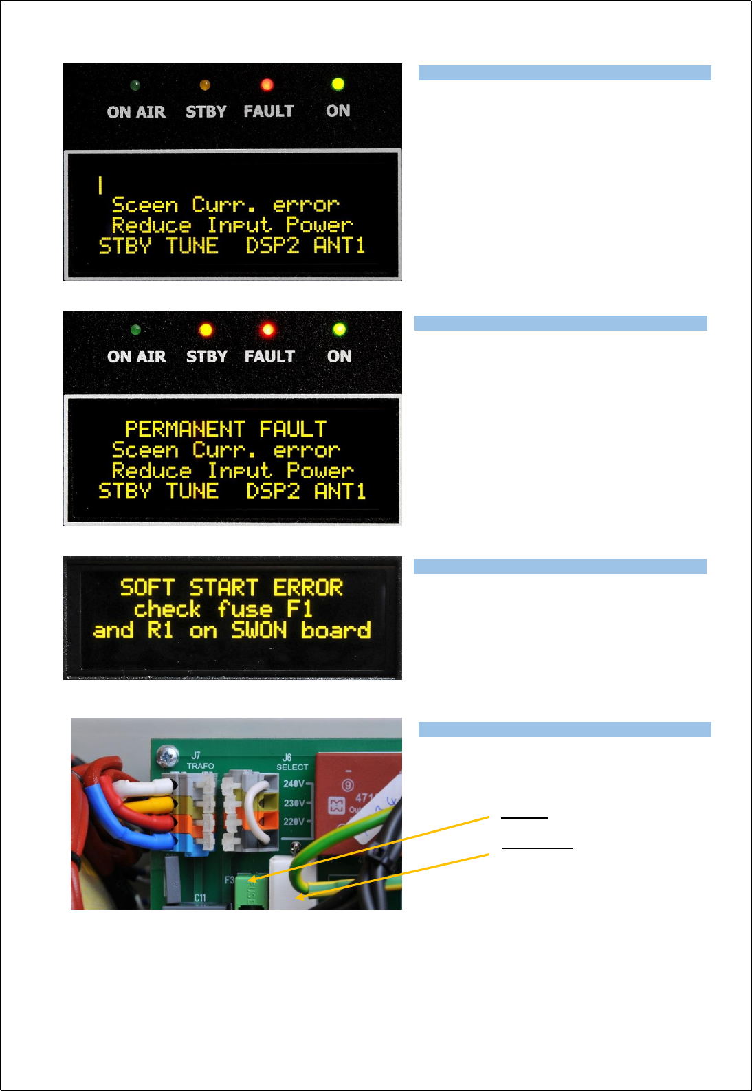
Exhibit 6 Page 30 from 35
An example shows situation when Input
power is too high. By pressing PTT safety
circuit will react quickly, error message
appears and FAULT LED starts blinking. In
this case screen current exceeds limited
value (60mA).
After abt. 1 sec. PA returns to TX mode.
Reduce Input power to avoid fault repeating.
This is the situation, when problem with high
Input power persists. Safety circuits reacted
3 times, and then switched PA to STBY mode.
Permanent fault appears.
To return PA to the normal operation,
decrease Input power first, then reset fault
status and go back to the OPER mode.
If resistor R1 or fuse F3 is damaged, safety
circuit stops starting of the PA and fault
message appears on the display. It is
necessary to replace the damaged
component.
Fuse F3
Resistor R1
If there is a fault condition, always try to remove the cause first. If it is not a hardware failure, it usually
succeeds. For example high VSWR, high Input power, mistune of PA, high temperature, etc.
Type of supported TCVR and working
frequency are visible on the display.
AUTO LED is ON.
Type of supported TCVR and working
frequency are visible on the display.
AUTO LED is ON.
Type of supported TCVR and working
frequency are visible on the display.
AUTO LED is ON.
Type of supported TCVR and working
frequency are visible on the display.
AUTO LED is ON.