Exhibit 6: User’s Manual External Radio Frequency Power Amplifier OM2000+ Model 2000+ Array Solutions 2611 North Beltline Rd Suite 109 Sunnyvale, Texas 75182 USA Tel: 214 954 7140 fax: 214 954 7142 E-mail: info@arraysolutions.
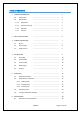
TABLE OF CONTENTS 1. GENERAL INFORMATION ..................................................................... 4 2.1. Introduction …………………………………………………………………. 4 2.2. Specification …………………………………………………………………. 4 2.2.1. Parameters …………………………………………………………………. 4 2.2.2. Protection Circuits …………………………………………………………………. 4 2.2.3. Indicators …………………………………………………………………. 5 2.2.4. Features …………………………………………………………………. 5 2. SAFETY INSTRUCTIONS …………………………………………………………………. 6 3.
6.2. Fuse Replacement …………………………………………………………………. 31 6.3. Tube Replacement …………………………………………………………………. 31 6.4. Cleaning …………………………………………………………………. 31 …………………………………………………………………. 32 7. APPENDIX 7.1. Primary AC selection …………………………………………………………………. 32 7.2. Removing the HV Transformer ……………………………………………………. 33 7.3.
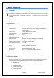
1. GENERAL INFORMATION 1.1. Introduction T he OM Power model OM2000+ is designed for all short wave amateur bands from 1.8 to 29.7 MHz (including WARC bands) plus 50 MHZ and all modes. It is equipped with a ceramic tetrode FU-728F. 1.2. Specification 1.2.1.
Grid current too high Grid voltage error Heating voltage error Mistuning of PA Temperature to high Soft start for fuses protection “switch-on blocking “ at opened amplifier 1.2.3.
2.
CAUTION The amplifier must be installed in such a way that free flow of hot air from the tube is allowed. The amplifier must not be installed in a constrained surrounding (i.e. tight shelves etc.). During long time operation ventilation grid can reach high temperature. Do not touch it! CAUTION The amplifier must be properly grounded during operation. CAUTION During operation the amplifier must be installed in such a way that the rear side remains accessible.
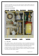
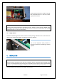
The output of the amplifier is a Pi-L circuit. The ceramic capacitor for TUNE and LOAD are divided. This enables the amplifier to be tuned exactly and makes it possible to easily return to the previously set positions after band changes. Top view on the opened OM2000+ Tetrode FU728F Antenna Switch Output Pi-L Circuit 3.2. Blower Tuning Capacitor Power Supply Board Subpanel Switch-ON Board HV transformer Power Supply Power amplifier is using one 3 KVA toroidal transformer.
Type of supported TCVR and working 3 kVA toroidal transformer is visible ondisplay. the left frequency are visible on the side. Switch-ON board is in the front, Power supply board behind it. AUTO LED is ON. CAUTION Primary section of the transformer is switchable for 220 - 240 VAC. Factory setting is 230VAC. If the AC voltage in your network is 220 or 240 Volts, you need to set the correct value before first starting of the PA. See part 7.1. for more information. 3.3.
4.1. Grounding CAUTION The amplifier has to be grounded properly! Connect the screw on the rear panel of the amplifier to your local grounding system with a copper cable; use a cross-section of 4 mm2 at least. Connect your transceiver to the same grounding system of your shack carefully! Use minimum length cables and make certain that the connections are both physically and electrically sound.
CAUTION If you are using an older transceiver or transmitters without time delay, we recommend to connect the PA in such a way that the transmit/receive switch (foot switch for example) is connected with the KEY IN socket of the amplifier. The KEY OUT socket is to be connected with the PTT socket at the transceiver. The amplifier is equipped with safety devices, which ensure that the output relay is not switched under power mistakenly (hot switching). KEY IN KEY OUT 4.4.
5. OPERATION WARNING! Before switching PA on, make sure that amplifier is grounded, antenna or dummy load is connected, and line cord is putted to the outlet. Be sure you selected AC input by 7.1. CAUTION Before switching PA on, check all connections between PA and TCVR. CAUTION Do not turn PA on for at least 2 hours after unpacking it and locating in its operating location.
BAND - Band selector switch TUNE - Anode capacitor for tuning (higher frequencies to "0"; lower frequencies to „100“). LOAD - Output capacitor tunes antenna load resistance to the amplifier. Capacity is low at „100“ and high at "0" on the scale. WATMETER - Analog double system meter for forward and reflected power measuring ON / OFF - Long press (abt. 1 sec.
ON AIR - Transmitting mode LED STBY - Standby mode LED FAULT - Failure LED ON - PA is „ON“ LED S1 - OPER / STBY - Press to switch between Standby and Operation mode ESC - Return to the previous level S2 - MENU DOWN - Enter the Menu - Scroll down S3 - DSP UP - Change display (DSP1, DSP2, DSP3) - Scroll up S4 - ANT ENT - Change Antenna output (ANT1, ANT2, ANT3) - Confirm the selection More functions of S1-S4 buttons will be described in next parts of this manual. 5.2.
If you change DSP during warming time, you lost count down information. Press BACK (S1) to restore starting message. When warming time expires, PA switches Type of supported TCVR and working itself automatically to the STBY mode. frequency are visible on the display. You have two possibilities now - switch PA to OPER mode and start operation, go AUTO OR LED to is ON. thru MENU and submenus to set display parameters, some hardware parameters or to enter the service menu.
After pressing MENU (S2) S1–S4 buttons changed their functions. To edit display Type of supported TCVR and working parameters, press DISP button. frequency are visible on the display. AUTO LED is ON. Press DIS1 to edit first display. Type of supported TCVR and working frequency are visible on the display. AUTO LED is ON. Now you can define parameters for first three rows. Start with first line, press 1Row button. Type of supported TCVR and working frequency are visible on the display. AUTO LED is ON.
S2 and S3 now changed their functions. To edit left sideofofsupported the second line,and press LEFT Type TCVR working button. frequency are visible on the display. AUTO LED is ON. Go UP or DOWN to select desired parameter. Press ENT to confirm selection. Type of supported TCVR and working frequency are visible on the display. AUTO LED is ON. If you finish left side settings, press ESC to go back to the side selection.
Electronic Bias Settings (EBS) is one of significant feature of the power amplifier. It allows to set low plate current after pressing the PTT regardless of whether you have CW or SSB mode, until RF signal is no present at the input. At the moment when RF signal comes to the input of PA, bias will automatically change to its working value. EBS level means level of the Input power, where EBS starts working. Default EBS value is 0.2 W. We recommend using EBS ON.
If you wish to restore factory default parameters, use UP or DOWN button to Type of supported TCVR and working select Restore default parameters. Then press ENT. frequency are visible on the display. AUTO LED is ON. Press YESType for 1ofsecond to confirm restoring. supported TCVR and working frequency are visible on the display. AUTO LED is ON. Use UP or DOWN button to select LCD contrast. Press ENT. Type of supported TCVR and working frequency are visible on the display. AUTO LED is ON.
Use Service menu after replacing the tube. This is step No. 1. Type of supported TCVR and working To enter Service menu, go to the MENU first, are visible on the display. then pressfrequency SERV button. AUTO LED is ON. Use UP or DOWN button to check software version. Type of supported TCVR and working frequency are visible on the display. AUTO LED is ON. Use UP or DOWN button to select Time ON parameter. Press ENT to see total operating TypePA.
Use UP or DOWN button to select Warnings. Press ENT to see warning numbers or letters Type in of chapter supported (see the table 6). TCVR and working frequency are visible on the display. AUTO LED is ON. Press ESC to go back to the Service menu. Type of supported TCVR and working frequency are visible on the display. AUTO LED is ON. Use this procedure after replacing the tube. This is step No. 2. of supported working Scroll UPType or DOWN to selectTCVR EBS1and settings.
Use UP or DOWN to select Calibration Ip & Is. Press ENTType to doofit.supported TCVR and working frequency are visible on the display. AUTO LED is ON. Ip and Is calibration runs in the background. Type of supported TCVR and working Result only is visible on the display. are visible Press ESC frequency to go one level back. on the display. AUTO LED is ON. 5.3. Operation mode CAUTION In STBY the amplifier is in bypass-mode and your transceiver is directly connected to the antenna.
Changing of DSP allows user to watch couple of basic parameters of the PA in operation mode without input RF signal. Notice: These Type of supported TCVR and working are three default display settings (software version 6.1.) frequency are visible on the display. AUTO LED is ON. Check all connections again. Set BAND selector, TUNE and LOAD capacitors according to TCVR parameters and delivered tuning table (see next part for more details). Apply low input power and press PTT. Check Analog wattmeter first.
5.4. Tuning of the Power Amplifier The OM2000+ power amplifier is operated in class AB. Thus it’s possible to obtain a maximum output power at excellent linearity. For this purpose the amplifier has to be tuned carefully. CAUTION The operation of a mistuned PA will cause malfunctions, the increase of grid current and problems with TVI/BCI. CAUTION If the input power is higher than 10W and the power amplifier is NOT correctly tuned, the safety devices will switch it to STBY.
Press OPER to enter operation mode. Apply low input power and press PTT. Be sure you selected right BAND, TUNE and LOAD knob positions. If you made some mistake, fault message appears: Safety circuit stopped transmitting, fault LED Type of supported TCVR working is ON (Fault code 4 is saving to theand memory). frequency are visible on the display. Release PTT, set proper positions of BAND, TUNE and LOAD according to the table and press PTT again. AUTO LED is ON.
Two of important information is visible – screen current increased, but still is within the allowed limits. Turn LOAD knob slightly Type of supported TCVR and working in arrows direction to get TUNE indicator between arrows. frequency are visible on the display. AUTO LED is ON. Display indicates correct tuning of the Power amplifier.Type of supported TCVR and working frequency are visible on the display. AUTO LED is ON. Remember Always use TUNE knob to get maximum output power.
To start the second method of fine tuning, press S2 (TUNE) button in OPER mode. PA is in the operation mode. After TUNE button (S2) was pressed, it changes its function. Now STOP is blinking. Type of supported TCVR and working Do not press STOP button yet! frequency are visible on the display. Apply input power according tune table (or lower) for selected band and press PTT. Use TUNE knob to AUTO LED is ON. get maximum output power. Use LOAD knob to get Is graph indicator within the boundaries.
6. MAINTENANCE 6.1. Indication of Fault Conditions If a fault condition appears during the operation of the amplifier, the safety circuits of OM2000+ will react. There are several warning or fault messages possible to appear on the display, when some of the protection will be activated. The OM2000+ power amplifier can report one of the following messages: 1 2 3 4 5 6 7 8 9 A B C D E F - Power Out is too high Refl.
them one position back. It means that every time last 30 messages are visible on the display. Next table shows limited values for the safety circuits activation. Fault code 1 Parameter Power Output is too high 2 3 4 5 6 7 8 9 A Reflected power is too high Power Input is too high Low output power (tune) Plate current is too high Grid current is too high Screen current is too high N/A Heating voltage error HARD FAULT (from 3.
An example shows situation when Input power is too high. By pressing PTT safety circuit will react quickly, error message appears and FAULT LED starts blinking. In this case screen current exceeds limited Type of supported TCVR and working value (60mA). visibletoonTX themode. display. After abt. frequency 1 sec. PAare returns Reduce Input power to avoid fault repeating. AUTO LED is ON. This is the situation, when problem with high Input power persists.
In the case of some hardware failure or if your power amplifier is not working properly, please contact the manufacturer or your dealer. WARNING! Never try to change or move any part inside the amplifier except of tube or fuses. Substitution of parts may void intrinsic safety! Manufacturer’s contacts: 6.2. OM POWER, s.r.o. 930 30 Báč 126 SLOVAKIA Email: om-power@om-power.com Fuse Replacement The user is allowed to change mains fuses (6.3 x 32mm), accessible from the rear panel, only.
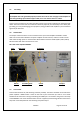
7. 7.1. APPENDIX Primary AC voltage selection Primary section of the HV transformer is switchable for three values of AC voltage (220, 230, 240V). Factory settings is 230VAC. Before first starting of the PA we recommend to check the correct value according to the AC voltage in your network. Change the settings, if necessary.
Remove the upper lid first. On the right side of the PA, next to the HV transformer there are two PCBs mounted. On the left upper side of the front (Switch-ON) board connector J6 is located. Use flat screwdriver or finger and press carefully the white stick to release contact and move upper end of the white jumper to the proper position, if necessary. Jumper must be connected between bottom contact and of remaining contacts. AC Typeone of supported TCVR and working voltage is marked next to every contact.
Weight of the PA was distributed (transformer has 12 kg, rest of the PA has cca 12 kg, too). Type of supported TCVR and working frequency are visible on the display. AUTO LED is ON. When refitting the transformer, watch to the correct location of individual sections and wires. NOTE Manufacturer reserves the right to make future changes in the way of connecting the transformer to the board. Allways mark the position of the terminals before disconnecting the transformer.
Exhibit 6 ON AC 1 INPUT K2 2 2 1 K1 Ext.